
Freelander Service Procedures
DRIVESHAFTS
47-10
REPAIRS
5. Release the CV joint from IRD flange by pulling
on the main casing of the CV joint . If
necessary, position a clamp around the CV
joint main body, release the CV joint by levering
between the clamp and the IRD flange. Support
the front of propeller shaft.
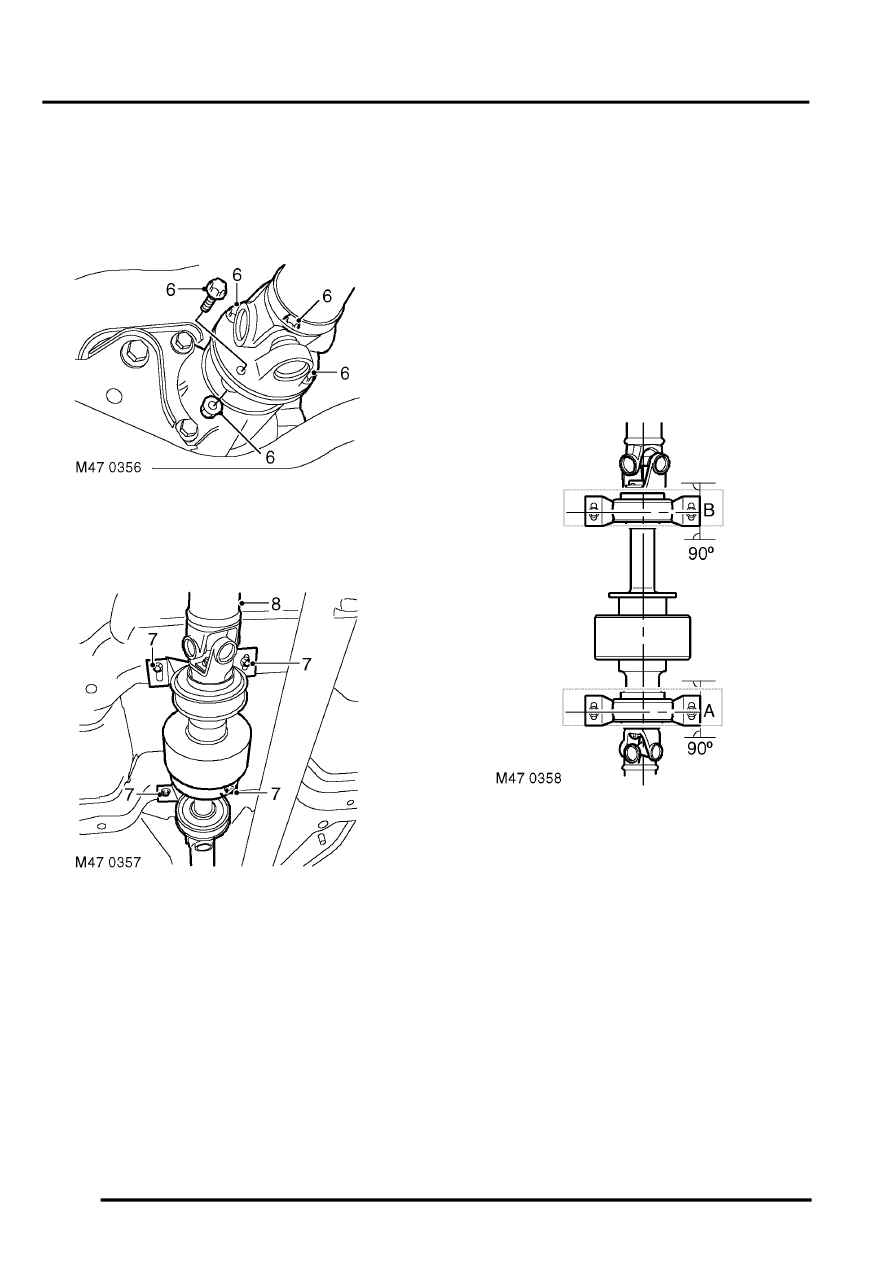
6. Remove 4 nuts and bolts securing propeller
shaft to rear axle flange, release and support
propeller shaft from rear axle flange.
7. Remove 4 bolts securing viscous coupling
support bearings.
CAUTION: Support the weight of viscous
coupling and propeller shaft.
8. With assistance remove complete propeller
shaft assembly.
Refit
1. Clean propeller shaft flanges and mating faces.
2. With assistance, fit propeller shaft assembly in
position, support front and rear propeller shafts
at each end.
3. Align viscous coupling support bearings, fit
bolts but do not tighten at this stage.
4. Position propeller shaft to rear axle and align
reference marks.
5. Fit and tighten nuts and bolt securing propeller
shaft to rear axle to 65 Nm (48 lbf.ft).
6. Position propeller shaft to IRD flange, align
flange reference marks.
7. Fit nuts and bolts securing front propeller shaft
to IRD flange and tighten to 40 Nm (30 lbf.ft).
8. Correctly position support bearings at 90
°
to the
centre line as shown at points 'A' and 'B' ,
tighten rear then front bolts to 28 Nm (21 lbf.ft).
9. Lower wheels.
10. Lower vehicle.