
Crankshaft (page 2 of 5)
- Make
- Land Rover
- Model
- Freelander Service Procedures
- Section
- OVERHAUL
ENGINE - K SERIES KV6
OVERHAUL 12-3-83
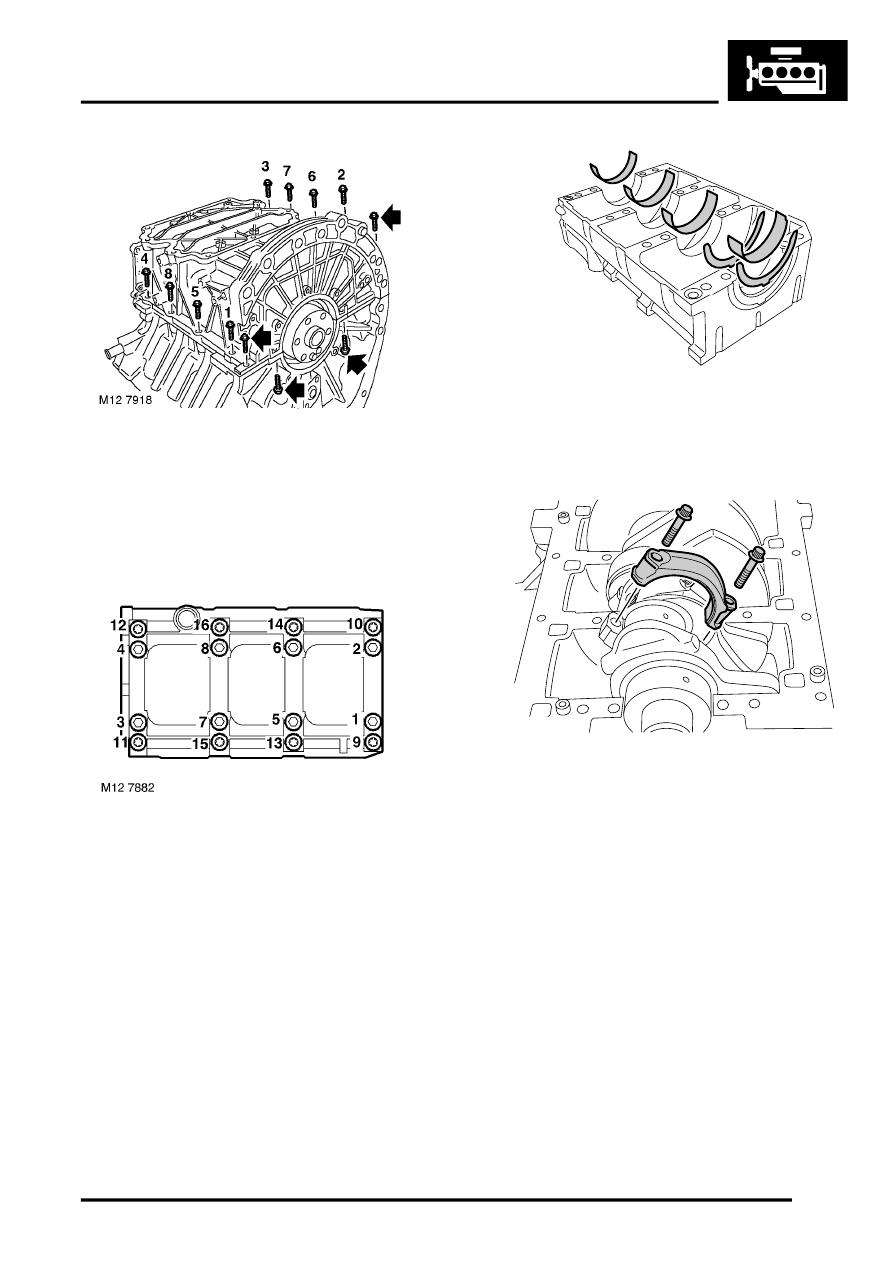
2. Using sequence shown, remove 8 M8 bolts
securing lower crankcase to cylinder block.
3. Remove remaining M8 bolt and 2 M6 bolts
securing lower crankcase to cylinder block.
4. Remove lower crankcase.
5. Using sequence shown, remove and discard 16
bolts securing bearing ladder to cylinder block.
NOTE: Short length bolts are fitted to the outer
edge of the bearing ladder.
6. Release bearing ladder from dowels and
remove from cylinder block.
7. Remove main bearing shells and 2 thrust
washer halves from bearing ladder, keep main
bearing shells in fitted order; discard thrust
washers.
8. Temporarily fit crankshaft pulley bolt.
9. Remove 4 dowel bolts and remove big end
bearing caps from No 1 and No 2 connecting
rods. Keep bearing caps in order.
NOTE: Number stamped below bearing cap
bolt is bearing bore size code. Number
stamped on connecting rod is cylinder number
and letter is weight code.
CAUTION: Do not remove cylinder clamps
LRT-12-144 unless pistons and connecting
rods are to be removed.
10. Release connecting rods from crankshaft.
11. Remove bearing shells from connecting rod
and cap.
12. Rotate crankshaft using pulley bolt, remove
bolts securing remaining connecting rod
bearing caps. Remove bearing caps and
bearing shells from caps. Keep bearing caps in
their fitted order.
M12 6858
M12 6835
Parts & tools for this job For Land Rover Freelander
- PARTEngine gasket setSearch: Land Rover Freelander engine gasket set
- TOOLTorque wrenchSearch: 3/8 inch torque wrench
- TOOLFeeler gauge setSearch: feeler gauge set
Links open Amazon search results in a new tab. As an Amazon Associate I earn from qualifying purchases.