
Piston assemblies - engine set
- Make
- Land Rover
- Model
- Freelander Service Procedures
- Section
- OVERHAUL › Piston assemblies - engine set
ENGINE - K SERIES KV6
OVERHAUL 12-3-77
OVERHAUL
Piston assemblies - engine set
$% 12.17.03.01
Disassembly
1. Remove crankshaft.
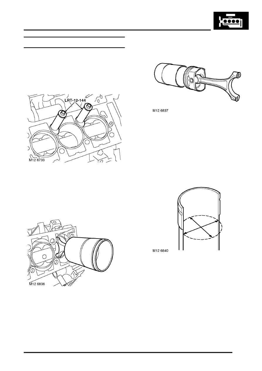
2. Remove LRT-12-144 cylinder liner clamps from
cylinder block.
3. Suitably identify each cylinder liner to its fitted
position in cylinder block.
4. With assistance, position cylinder block to
enable each piston and cylinder liner to be
removed.
5. Carefully push each piston assembly and
cylinder liner from cylinder block.
CAUTION: Suitably identify each piston with
its respective cylinder liner.
6. Remove piston assemblies from liners, keep
liners in their fitted order.
7. Refit caps onto connecting rods, lightly tighten
dowel bolts.
8. Using a suitable expander, remove and discard
piston rings from each piston.
9. Using a squared off end of an old piston ring,
remove carbon from piston ring grooves.
Inspect
1. Cylinder liner bores: Measure wear and taper
in two axis 65 mm (2.5 in) from top of cylinder
liner bore The cylinder liner grade is marked on
outside diameter of liner.
CAUTION: Cylinder liners with excessively
glazed, worn, scratched or scored bores
must be replaced. DO NOT attempt to hone
or remove glazing from bore. Ensure that if
original liners are to be refitted, reference
marks made during dismantling are not
erased.
Parts & tools for this job For Land Rover Freelander
- PARTEngine gasket setSearch: Land Rover Freelander engine gasket set
- TOOLTorque wrenchSearch: 3/8 inch torque wrench
- TOOLFeeler gauge setSearch: feeler gauge set
Links open Amazon search results in a new tab. As an Amazon Associate I earn from qualifying purchases.