L322 Range Rover System Description and Operation

MANIFOLDS AND EXHAUST SYSTEM – V8
30-2-4
DESCRIPTION AND OPERATION
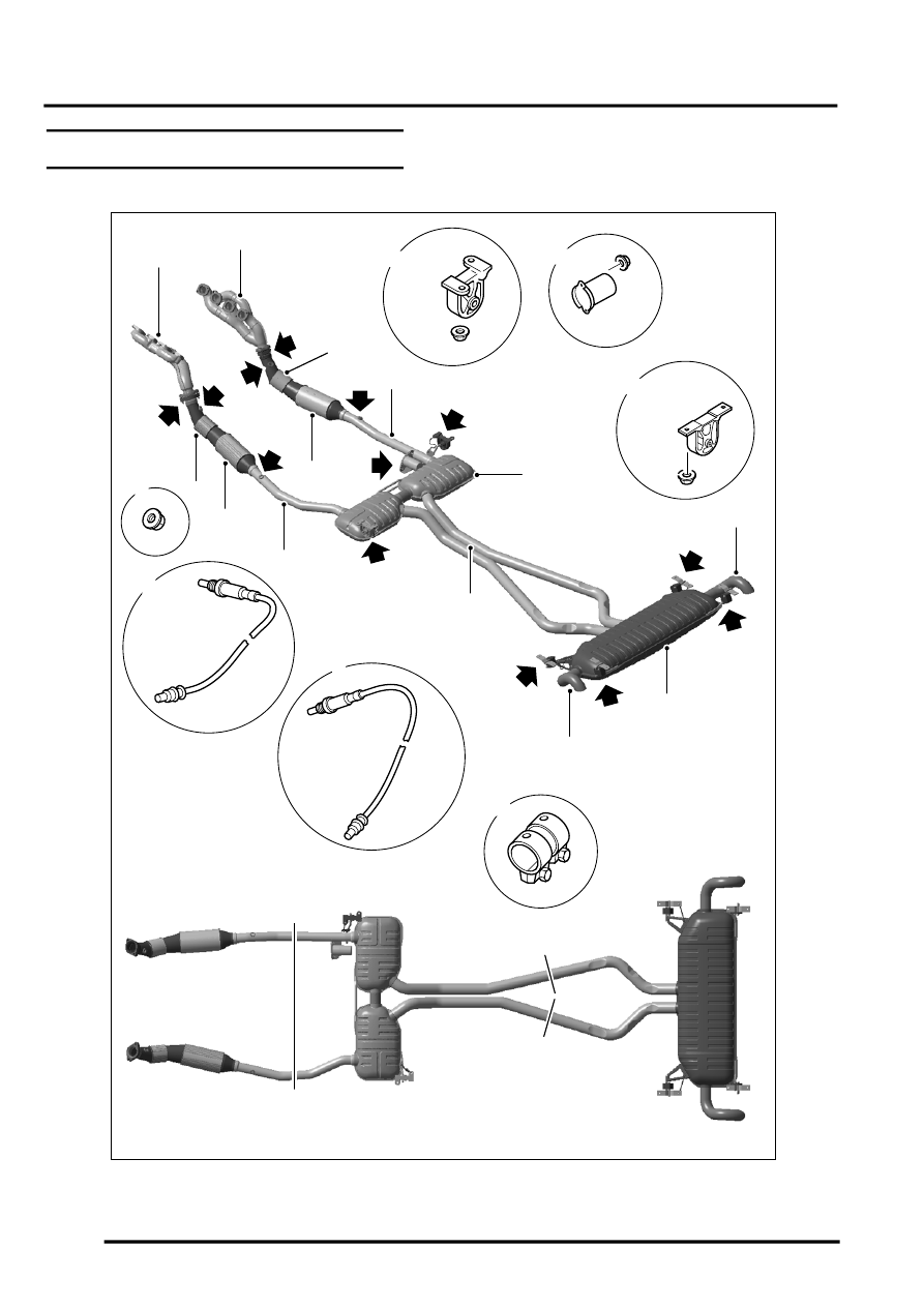
Exhaust System Component Layout
X = Forward cut point; Y = Rear cut point
M30 1153
1
2
5
6
7
9
4
7
5
6
8
11
12
13
11
14
14
15
14
16
14
15
4
7
3
3
10
14
3
10
11
17
7
x
x
y
y
