
B3000 SE Regular Cab 4WD V6-3.0L OHV (1998)
If the marks are on opposite sides of the propeller shaft, the yoke or axle companion flange is responsible for the vibration.
When replacing an axle companion flange, the propeller shaft runout must not exceed 0.89 mm (0.035 inch). When runout is within limits, recheck
for vibration at road speed. If vibration persists, balance the propeller shaft.
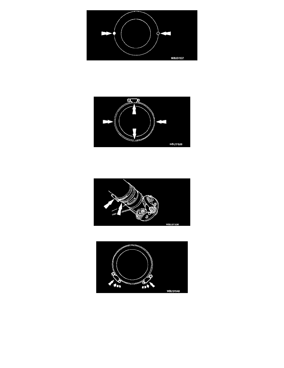
7. To balance the propeller shaft, install one or two hose clamps on the propeller shaft, near the rear. Position of the hose clamp head(s) can be
determined by trial-and-error.
8. Mark the rear of the propeller shaft into four approximately equal sectors and number the marks 1 through 4. Install a hose clamp on the propeller
shaft with its head at position No. 1.
Check for vibration at road speed. Recheck with the clamp at each of the other positions to find the position that shows minimum vibration. If two
adjacent positions show equal improvement, position the clamp head between them.
9. If the vibration persists, add a second clamp at the same position and recheck for vibration.
If no improvement is noted, rotate the clamps in opposite directions, equal distances from the best position determined in Step 8. Separate the
clamp heads about 13 mm (1/2 inch) and recheck for vibration at the road speed.
Repeat the process with increasing separation until the best combination is found or the vibration is reduced to an acceptable level.
10. Install the wheels and road test (vibration noticeable on the hoist may not be evident during the road test). If the vibration is still not acceptable,
replace the axle drive line vibration damper first, if so equipped.