
Step 1
- Make
- Mazda
- Model
- MX-5 (NA) Factory Workshop Manual
- Year
- 1990–1992
- Section
- Flowchart No. 4 (T) › Step 1
Body electrical systemStep 1
Caution
• Before troubleshooting, read SERVICE PRECAUTION on page T–133.
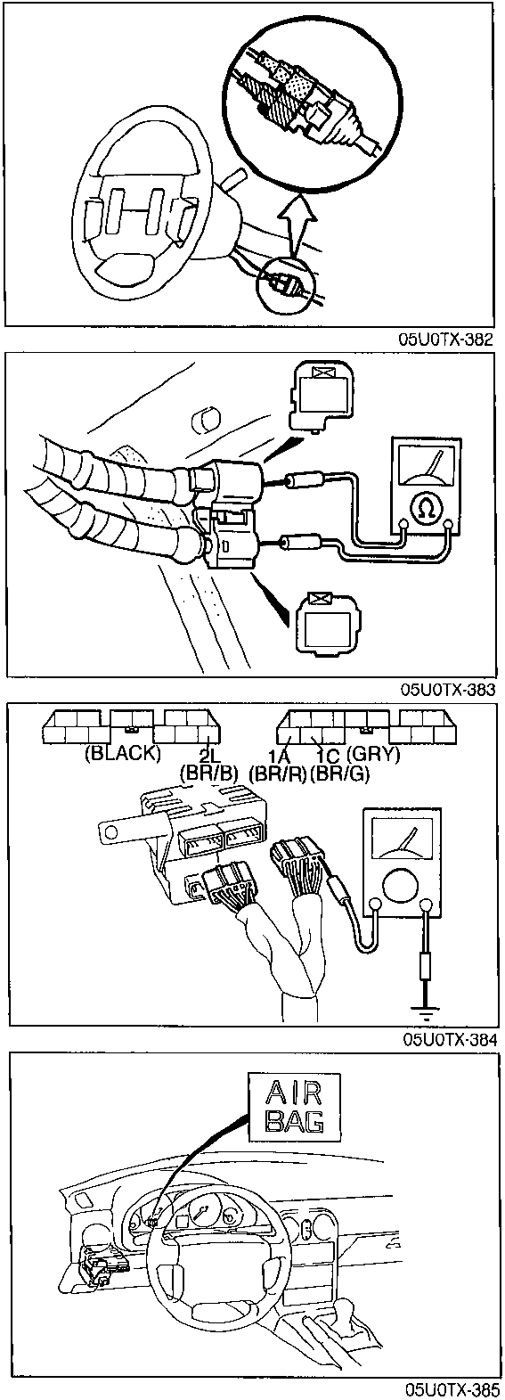
Step 1
- Disconnect the negative battery cable.
- Remove the knee protector, and disconnect the clock spring connectors (Orange and blue).
- Disconnect all D-sensor (CNT, LH and RH) connectors, and measure the resistance of each sensor.
Resistance: Approx. 1.2 kΩ
- If not as specified, replace the sensor, then go to Step 3.
- If correct, go to Step 2.
Step 2
- Reconnect all D-sensor connectors.
- Disconnect the diagnostic module connector.
- Measure the resistance between the following terminal-wires of the diagnostic module connector and a body ground.
| Terminal-wire | Resistance | Action |
|---|---|---|
| 1C (BR/G) | Approx. 1.2 kΩ | Next, check terminal-wire 1A (BR/R) |
| Other 1.2 kΩ | Replace wire harness, then go to Step 3 | |
| 1A (BR/R) | Approx. 1.2 kΩ | Next, check terminal-wire 2L (BR/B) |
| Other 1.2 kΩ | Replace wire harness, then go to Step 3 | |
| 2L (BR/B) | Approx. 1.2 kΩ | Go to Step 3 |
| Other 1.2 kΩ | Replace wire harness, then go to Step 3 |
Step 3
- Reconnect the diagnostic module connector.
- Reconnect the clock spring connector.
- Reconnect the negative battery cable.
- Turn the ignition switch ON, and monitor the warning lamp operation.
- If the warning lamp flashes ten times again, replace the diagnostic module.
Parts & tools for this job For 1990 Mazda MX-5
- TOOLDigital multimeterSearch: automotive digital multimeter
- PARTAssorted fuse kitSearch: car fuse assortment kit
- TOOLWire crimper and connector kitSearch: wire crimper connector kit
Links open Amazon search results in a new tab. As an Amazon Associate I earn from qualifying purchases.