
Routing diagram
- Make
- Mazda
- Model
- MX-5 (NA) Factory Workshop Manual
- Year
- 1990–1992
- Section
- Z Wiring diagram › Routing diagram
Wiring diagramRouting diagram
Routing diagram
- This shows where electrical components are located on the system circuit diagram by lead and connector symbols.
- Specified values are listed beside the routing diagram or on the following page.
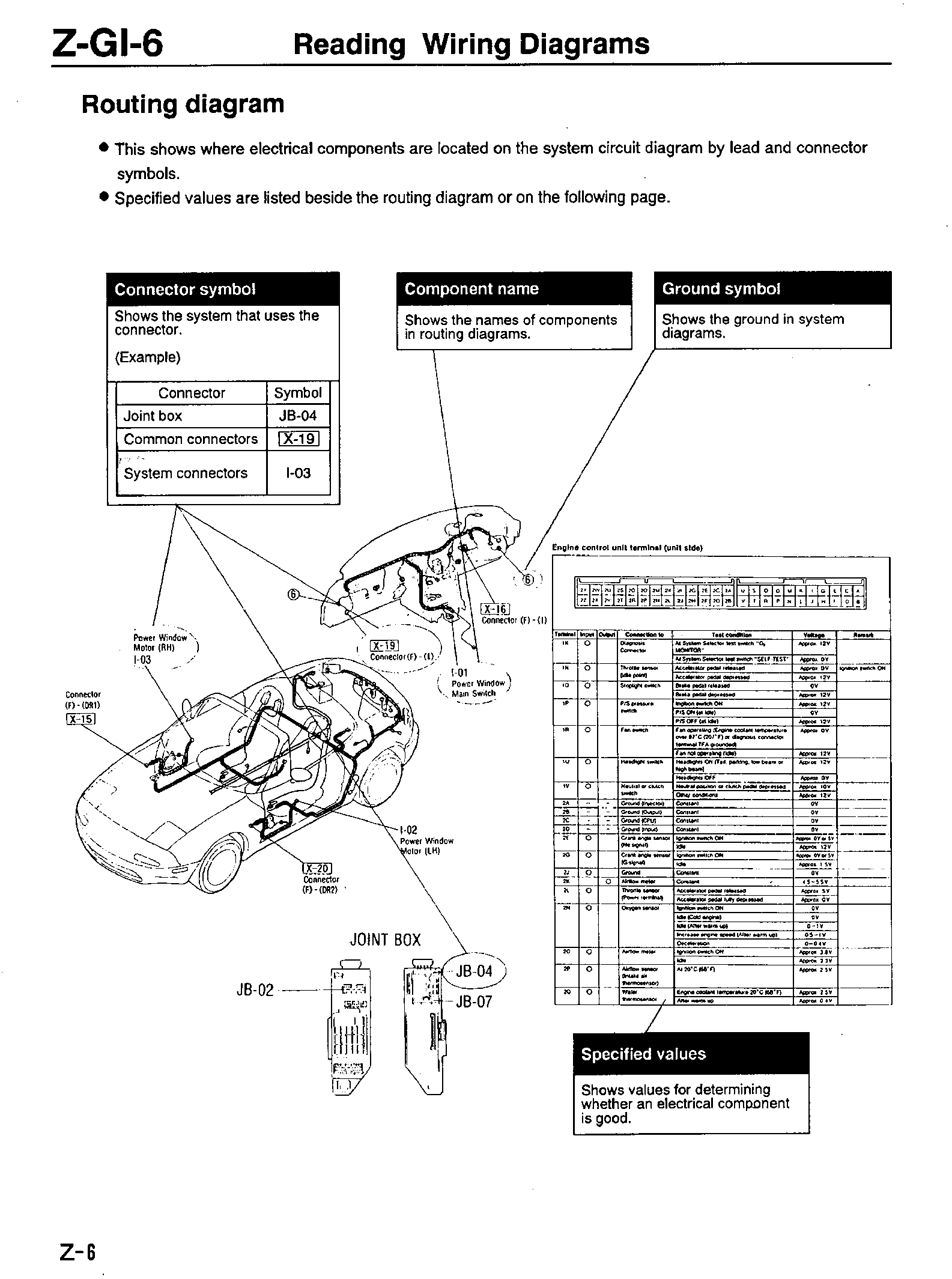
| Connector symbol | ||
|---|---|---|
| Shows the system that uses the connector. | ||
| (Example) | ||
| Connector | Symbol | |
| Joint box | JB-04 | |
| Common connectors | X-19 | |
| System connectors | I-03 | |
| Component name | |
|---|---|
| Shows the names of components in routing diagrams. |
| Ground symbol | |
|---|---|
| Shows the ground in system diagrams. |
| Terminal | Input | Output | Connection to | Test condition | Voltage | Remark |
|---|---|---|---|---|---|---|
| 1K | O | Diagnosis Connector | At System Selector test switch "ON MONITOR" | Approx 12V | ||
| 1N | O | Throttle sensor (idle point) | At System Selector test switch "SELF TEST" Accelerator pedal released Accelerator pedal depressed | Approx 0V Approx 0V Approx 12V | Ignition switch ON | |
| 1O | O | Stoplight switch | Brake pedal released Brake pedal depressed | 0V Approx 12V | ||
| 1P | O | P/S pressure switch | Ignition switch ON P/S ON (at idle) P/S OFF (at idle) | Approx 12V 0V Approx 12V | ||
| 1R | O | Fan switch | Fan operating (Engine coolant temperature over 87°C (201°F) or diagnosis connector terminal TFA grounded) Fan not operating (idle) | Approx 0V Approx 12V | ||
| 1U | O | Headlight switch | Headlights OFF (Tail, parking, low beam or high beam) | Approx 12V | ||
| 1V | O | Neutral or clutch switch | Headlights OFF Neutral position or clutch pedal depressed Other conditions | Approx 0V Approx 10V Approx 12V | ||
| 2A | -- | -- | Ground (Injector) | Constant | 0V | |
| 2B | -- | -- | Ground (Output) | Constant | 0V | |
| 2C | -- | -- | Ground (CPU) | Constant | 0V | |
| 2D | -- | -- | Ground (Input) | Constant | 0V | |
| 2E | O | Crank angle sensor (Ne signal) | Ignition switch ON | Approx 0V at 5V Approx 12V | ||
| 2G | O | Crank angle sensor (IG signal) | Ignition switch ON Idle | Approx 0V at 5V Approx 1.5V | ||
| 2J | Ground | Constant | 0V | |||
| 2K | O | Airflow meter | Constant | +5 ~ +5.5V | ||
| 2L | O | Throttle sensor (Power terminal) | Accelerator pedal released Accelerator pedal fully depressed | Approx 5V Approx 0V | ||
| 2N | O | Oxygen sensor | Ignition switch ON Idle (Cold engine) Idle (After warm up) Increase engine speed (After warm up) Deceleration | 0V 0V 0.5 ~ 1V 0 ~ 0.4V | ||
| 2O | O | Airflow meter | Ignition switch ON Idle | Approx 3.8V Approx 3.3V | ||
| 2P | O | Airflow sensor (Resist air thermosensor) | At 20°C (68°F) | Approx 2.5V | ||
| 2Q | O | Water thermosensor | Engine coolant temperature 20°C (68°F) After warm up | Approx 2.5V Approx 0.4V |
| Specified values | |
|---|---|
| Shows values for determining whether an electrical component is good. |
Parts & tools for this job For 1990 Mazda MX-5
- TOOLDigital multimeterSearch: automotive digital multimeter
- PARTAssorted fuse kitSearch: car fuse assortment kit
- TOOLWire crimper and connector kitSearch: wire crimper connector kit
Links open Amazon search results in a new tab. As an Amazon Associate I earn from qualifying purchases.