
System circuit diagram/connector diagram
- Make
- Mazda
- Model
- MX-5 (NA) Factory Workshop Manual
- Year
- 1990–1992
- Section
- Z Wiring diagram › System circuit diagram/connector diagram
Wiring diagramSystem circuit diagram/connector diagram
System circuit diagram/connector diagram
- These show the circuits for each system, from the power supply to the ground. The power supply side is at the top of the page and the ground side is at the bottom. The diagrams describe circuits with the ignition switch OFF.
Below is an explanation of the various points in the diagram.
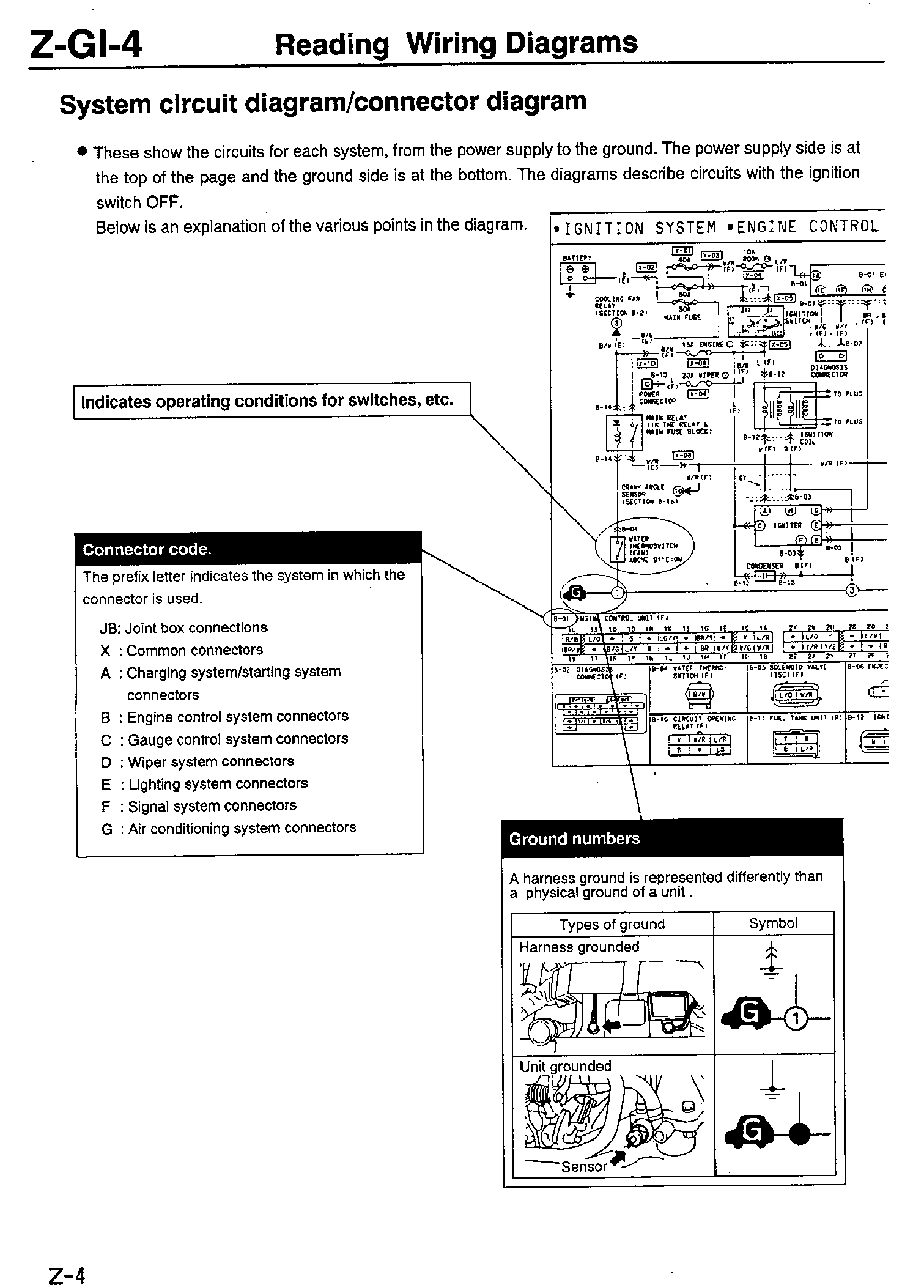
Connector code.
The prefix letter indicates the system in which the connector is used.
JB: Joint box connections
X : Common connectors
A : Charging system/starting system connectors
B : Engine control system connectors
C : Gauge control system connectors
D : Wiper system connectors
E : Lighting system connectors
F : Signal system connectors
G : Air conditioning system connectors
Ground numbers
A harness ground is represented differently than a physical ground of a unit.
| Types of ground | Symbol |
|---|---|
| Harness grounded | [Image: Ground symbol showing wire connected to chassis with G1] |
| Unit grounded Sensor |
[Image: Ground symbol showing component body connected to ground with G] |
Parts & tools for this job For 1990 Mazda MX-5
- TOOLDigital multimeterSearch: automotive digital multimeter
- PARTAssorted fuse kitSearch: car fuse assortment kit
- TOOLWire crimper and connector kitSearch: wire crimper connector kit
Links open Amazon search results in a new tab. As an Amazon Associate I earn from qualifying purchases.