
Gearbox adaption
- Make
- MG
- Model
- MGF Stepspeed EM-CVT Automatic Gearbox Workbook
- Section
- Gearbox adaption
The ECM knows the shape of the profile and monitors the actual engine speed relative to the mapped engine speed. The ECM learns, through historical control, a new profile which is more representative to the actual transmission characteristics. The ECM also monitors the amount this line moves from the mapped line, as long as this difference is within its tolerance band, the ECM accepts the value and learns from it. If the actual value goes beyond the adaptive tolerance the ECM will perform a reset. If the value still exceeds the adaptive tolerance band, the ECM will store a fault code and place the transmission into its default position.
Gearbox adaption
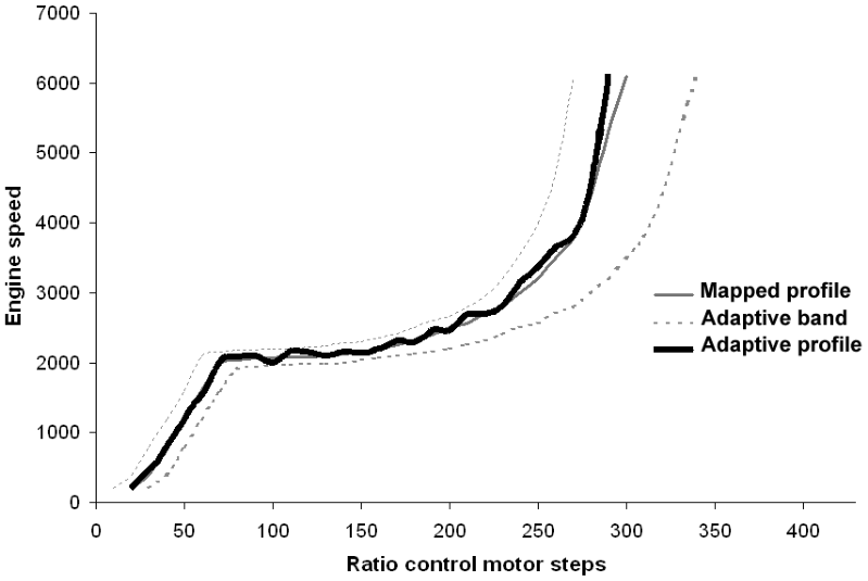
Figure 35
The figures quoted are only representative, due to the nature of the adaption, these may or may not be correct.
When setting the fast adaption, the control system will initially target 5,000 rpm in order to learn the ratio control motor position at this engine speed. Once the vehicles powertrain is stable enough for an adaption to take place, the ratio control motor position is noted and the control system will target 4,500 rpm. This process continues subsequently targeting 4,000, 3,500, 3,000, 2,500, 2,000, 1,900, 1,800, 1,700, 1,600, 1,500, 1,400. When the 1,400 rpm point has been adapted, normal operation will commence.
To set the fast adaption procedure drive the car, on a level road, at around 60 km/h in Em-CVT drive mode, and then lift off the throttle. As the vehicle decelerates (do not use the brakes) the adaptions will occur. If the vehicle speed drops too far before the process is complete, the engine speed will drop from its targeted speed back towards idle. The liquid crystal display (LCD) will continue to flash ’F’, and the transmission will not operate normally. If this happens, simply repeat the process by accelerating back to 60 km/h and lift off the throttle again to give the software a chance of learning the remaining points. When the procedure is complete, the display will stop flashing.
Parts & tools for this job For MG MGF
- TOOLTorque wrenchSearch: 3/8 inch torque wrench
- TOOLSocket setSearch: socket set metric
- BOOKHaynes manualSearch: Haynes manual MG MGF
Links open Amazon search results in a new tab. As an Amazon Associate I earn from qualifying purchases.