
PB 150 V8-318 5.2L VIN T 2-BBL (1983)
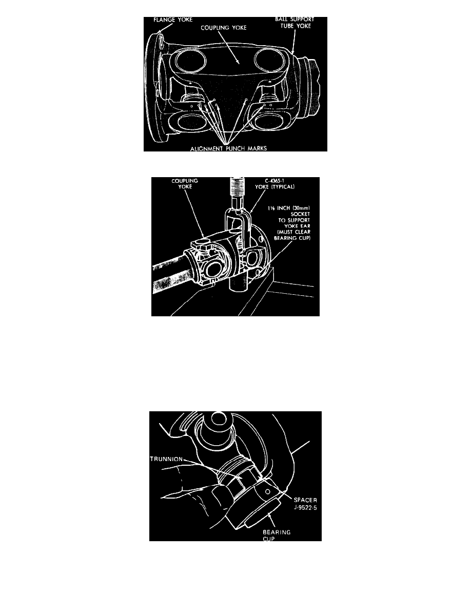
Fig. 11 Alignment punch marks
Fig. 12 Cross press being used in place of socket
DISASSEMBLY
CONSTANT VELOCITY JOINT
To disassemble the constant velocity joint, the bearings should be removed in sequence shown. This method requires the least amount of work.
1. Mark all yokes before disassembly as shown, so that they can be reassembled in their original relationship to maintain driveshaft balance. The
following procedure can be performed in a vise and a cross press tool, can be used in place of the socket used to drive the bearings.
2. Support the driveshaft horizontally in line with the base plate of a press. Place rear end of coupling yoke over a 1-1/8 inch socket to accept the
bearing. Place a socket slightly smaller than the bearing on the opposite side of the spider.
Fig. 13 Using spacer to completely drive out bearing