
Cruise Control: Diagrams (page 27 of 131)
- Make
- Pontiac
- Model
- G8
- Engine
- V8-6.0L
- Year
- 2009
- Section
- Diagrams
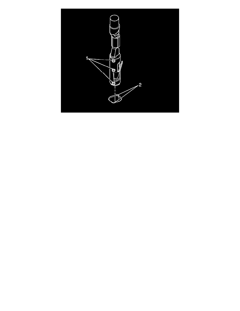
1. Prior to installation the terminal must be aligned so the (1) coding lugs align with the (2) coding grooves on the connector.
2. Once the terminal is aligned, slide the terminal into the cavity until the retainer has engaged in the cavity of the connector.
3. Slide the TPA in the connector body and seat it using a small flat bladed tool. The TPA is seated when it is flush with the contact housing.
4. Secure the wires to the connector body using a tie wrap and replace the dress cover and grommet.
Bosch Connectors (2.8 JPT)
Bosch Connectors (2.8 JPT)
Special Tools
J-38125 Terminal Repair Kit
Terminal Removal Procedure
1. Pull out the slider on the connector position assurance (CPA) until it is at the end of its travel.
2. Disconnect the connector from the component.
3. Remove the wire dress cover, if necessary.
4. Push the wire side of the terminal that is being removed toward the connector and hold it in position.
Pinch or Ctrl + scroll to zoom. Double-tap to reset.
Parts & tools for this job For 2009 Pontiac G8 6.0L
- TOOLOBD2 scannerSearch: OBD2 scanner
- TOOLDigital multimeterSearch: automotive digital multimeter
- TOOLBack-probe test leadsSearch: back probe test leads
Links open Amazon search results in a new tab. As an Amazon Associate I earn from qualifying purchases.