
Cruise Control: Diagrams (page 127 of 131)
- Make
- Pontiac
- Model
- G8
- Engine
- V8-6.0L
- Year
- 2009
- Section
- Diagrams
10. Start in the middle and gradually move the heat barrel to the open ends of the tubing:
*
The tubing will shrink completely as the heat is moved along the insulation.
*
A small amount of sealant will come out of the end of the tubing when sufficient shrinkage is achieved.
Splicing Inline Harness Diodes
Splicing Inline Harness Diodes
Many vehicle electrical systems use a diode to isolate circuits and protect the components from voltage spikes. When installing a new diode use the
following procedure.
1. Open the harness.
*
If the harness is taped, remove the tape.
*
To avoid wiring insulation damage, use a sewing ripper in order to cut open the harness.
*
If the harness has a black plastic conduit, pull out the diode.
2. If the diode is taped to the harness, remove all of the tape.
3. Check and record the current flow direction and orientation of diode.
4. Remove the inoperative diode from the harness with a suitable soldering tool.
Note: If the diode is located next to a connector terminal remove the terminal(s) from the connector to prevent damage from the soldering tool.
5. Carefully strip away a section of insulation next to the old soldered portion of the wire(s). Do not remove any more than is needed to attach the
new diode.
6. Check current flow direction of the new diode, being sure to install the diode with correct bias. Reference the appropriate service manual wiring
schematic to obtain the correct diode installation position.
7. Attach the new diode to the wire(s) using 60/40 rosin core solder. Before soldering attach some heat sinks (aluminum alligator clips) across the
diode wire ends to protect the diode from excessive heat. Follow the manufacturer's instruction for the soldering equipment.
8. Reinstall terminal(s) into the connector body if previously removed.
Note: To prevent shorts to ground and water intrusion, completely cover all exposed wire and diode attachment points with tape.
9. Tape the diode to the harness or connector using electrical tape.
Splicing Twisted or Shielded Cable
Splicing Twisted or Shielded Cable
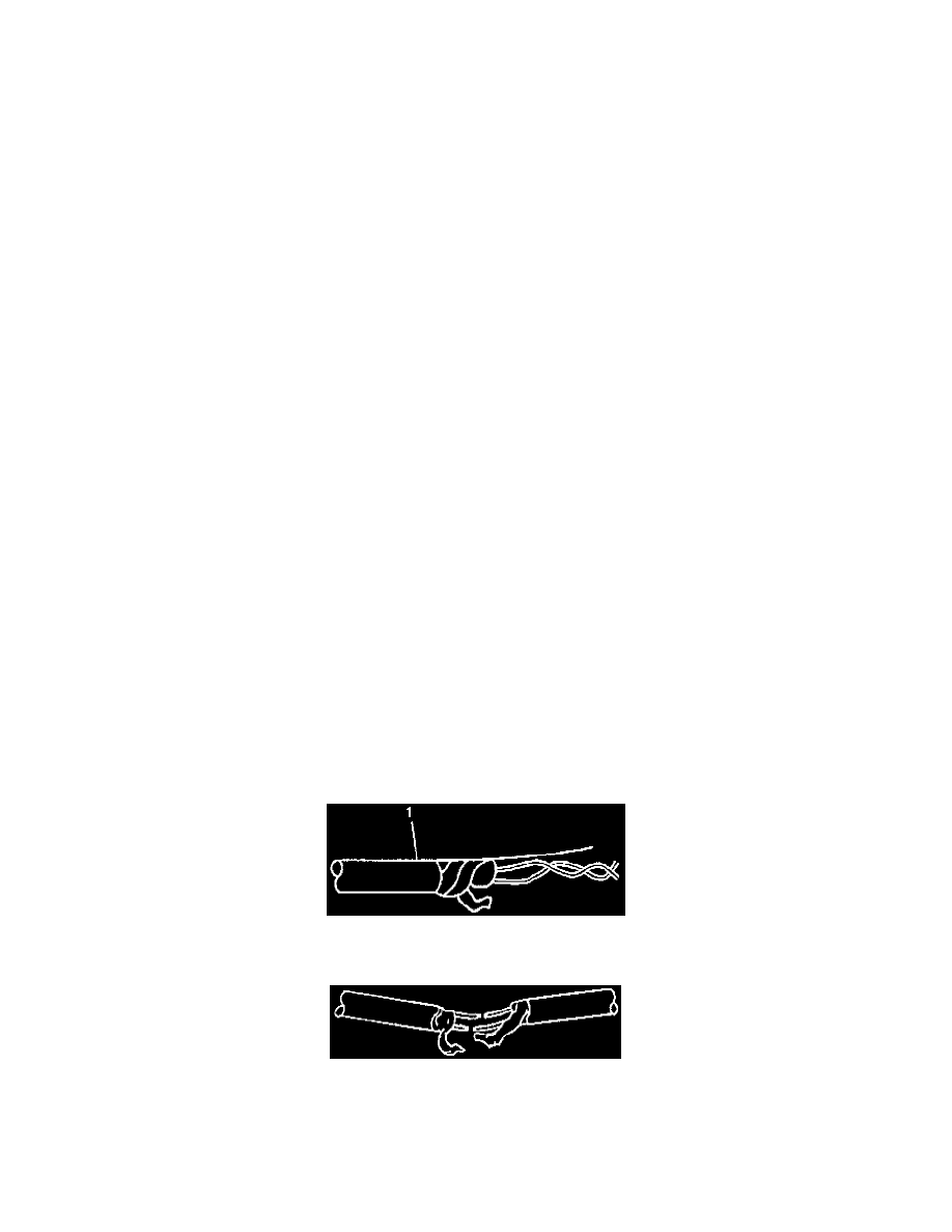
Twisted/shielded cable is used in order to protect wiring from electrical noise. Two-conductor cable of this construction is used between the radio and
the Delco-Bose(R) speaker/amplifier units and other applications where low level, sensitive signals must be carried. Follow the instructions below in
order to repair the twisted/shielded cable.
1. Remove the outer jacket (1). Use care not to cut into the drain wire of the mylar tape.
2. Unwrap the tape. Do not remove the tape. Use the tape in order to rewrap the twisted conductors after the splice is made.
3. Prepare the splice. Untwist the conductors and follow the instructions for Splicing Copper Wire Using Splice Sleeves (See: Testing and
Inspection/Component Tests and General Diagnostics). Staggering the splices by 65 mm (2.5 in) is recommended.
Pinch or Ctrl + scroll to zoom. Double-tap to reset.
Parts & tools for this job For 2009 Pontiac G8 6.0L
- TOOLOBD2 scannerSearch: OBD2 scanner
- TOOLDigital multimeterSearch: automotive digital multimeter
- TOOLBack-probe test leadsSearch: back probe test leads
Links open Amazon search results in a new tab. As an Amazon Associate I earn from qualifying purchases.