
’K16’ flow diagram (Cooling system - K Series)
- Make
- Rover
- Model
- 200 Workshop Manual
- Year
- 1995–1999
- Section
- Description and operation › ’K16’ flow diagram
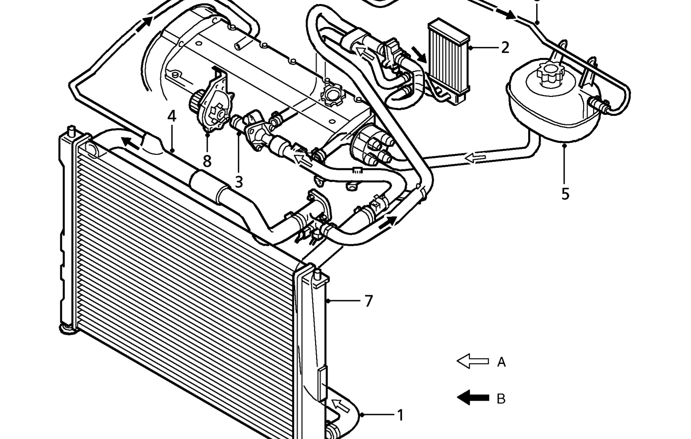
’K16’ flow diagram
A = COLD B = HOT
Any excess coolant created by heat expansion is returned to the expansion tank (5) via hose (6).
The radiator (7) is a copper/brass cross-flow type with moulded plastic end tanks which incorporate sensor mountings and is mounted on rubber bushes directly into the front body member. The top of the radiator is supported by means of mounting brackets bolted to the radiator and bonnet locking platform.
For additional air flow, at times when the vehicle is stationary, an electric cooling fan is fitted. This is triggered by the Engine Control Module (ECM) on ’K’ Series models or by a coolant temperature sensor at the rear of the cylinder block.
The coolant pump (8) is a rotor type pump which draws coolant directly from the thermostat. The pump is driven by a geared pulley from the camshaft timing belt.
Parts & tools for this job For 1995 Rover 200
- FLUIDCoolantSearch: Rover coolant antifreeze
- PARTThermostatSearch: Rover 200 1995 thermostat
- TOOLCooling system pressure testerSearch: cooling system pressure tester
Links open Amazon search results in a new tab. As an Amazon Associate I earn from qualifying purchases.