
Deployment of driver airbag module (page 2 of 2)
- Make
- Rover
- Model
- 200 Workshop Manual
- Year
- 1995–1999
- Section
- Precautions
Restraint systemsDeployment of driver airbag module · page 2 of 2
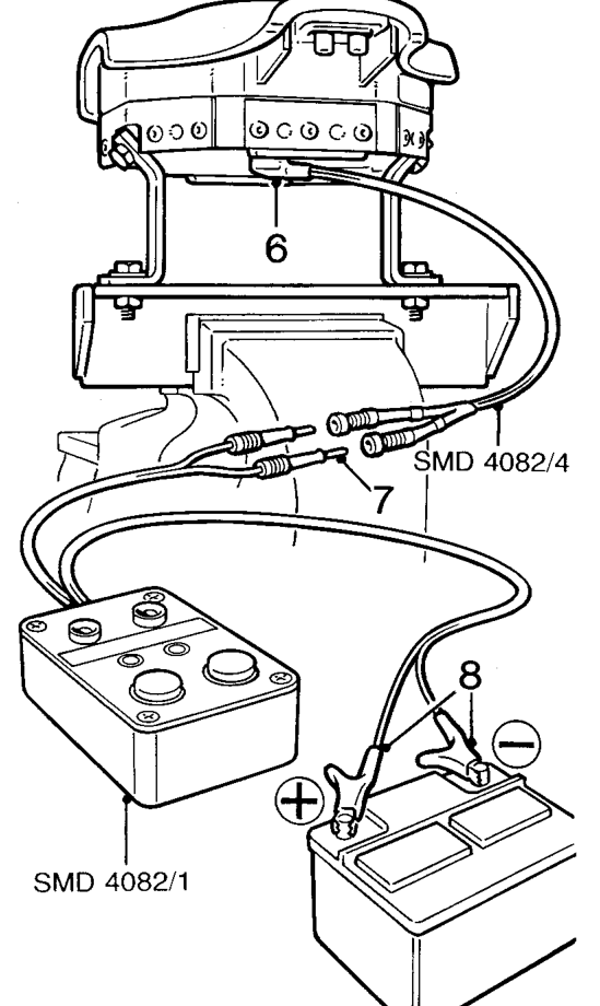
- Connect flylead SMD 4082/4 to airbag module.
- Connect flylead SMD 4082/4 to tool SMD 4082/1.
WARNING: Do not lean over airbag module whilst connecting.
- Connect tool SMD 4082/1 to battery.
WARNING: Ensure all personnel are standing at least 15 metres away from module.
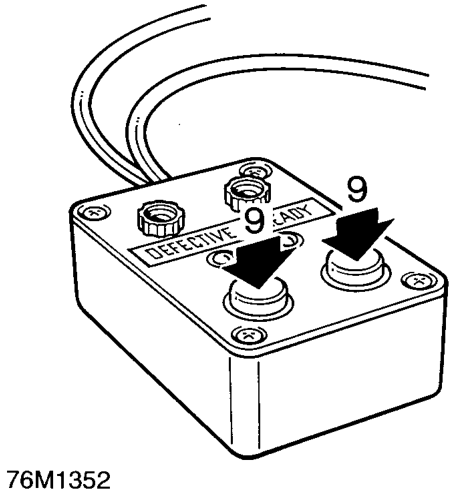
- Press both operating buttons to deploy airbag module.
- DO NOT return to airbag module for 30 minutes.
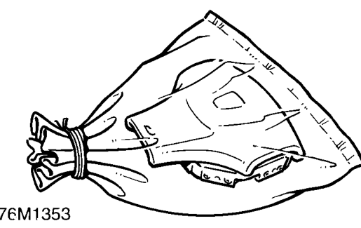
- Using gloves and face mask, remove airbag module from tool, place airbag module in plastic bag, and seal bag.
- Wipe down tool with damp cloth.
- Transport deployed airbag module to designated area for incineration.
NOTE: DO NOT transport airbag module in the vehicle passenger compartment.
- Scrap all remaining parts of airbag system. DO NOT re-use or salvage any parts of the airbag system.
Parts & tools for this job For 1995 Rover 200
- TOOLOBD2 scannerSearch: OBD2 scanner
- TOOLDigital multimeterSearch: automotive digital multimeter
- TOOLBack-probe test leadsSearch: back probe test leads
Links open Amazon search results in a new tab. As an Amazon Associate I earn from qualifying purchases.