
Downshift cable adjust (Automatic gearbox)
- Make
- Rover
- Model
- 400 Workshop Manual
- Year
- 1995–2000
- Section
- Adjustments › Downshift cable adjust
Automatic gearboxDownshift cable adjust
DOWNSHIFT CABLE ADJUST
Service repair no - 44.30.02
Adjust
NOTE: Before adjusting the downshift cable make sure:
- Throttle free play is correct.
- Idle speed is correct.
- Engine is at normal working temperature.
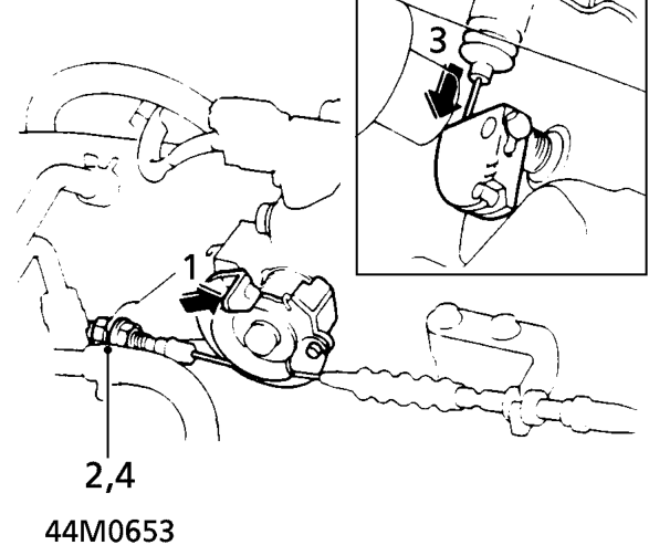
- Check that cable is secure in its clip and throttle is fully closed.
- Loosen the downshift cable locknut at the throttle linkage.
- While pushing the downshift cam to the fully closed position, adjust cable to take out free play.
- Tighten cable locknut.
SELECTOR CABLE ADJUST
Service repair no - 44.30.04
Adjust
CAUTION: For safety precautions refer to SRS section.
- Remove front console. See BODY, Interior trim components.
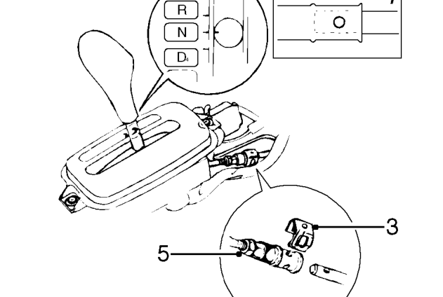
- Move selector to ’N’ position.
- Remove lock pin from cable adjuster.
- Fit a 4 mm diameter slave pin through hole in selector cable and adjuster to check for alignment. If binding is felt as pin passes through, cable is out of adjustment.
- Slacken cable locknut.
- Remove slave pin.
- Rotate adjuster until pin passes through both holes without binding.
NOTE: Selector cable has holes at 901 ° intervals to allow adjustment in /4 turn increments.
- With slave pin in position, tighten locknut to 7 Nm.
- Remove slave pin and refit lock pin.
- Move selector lever through its working arc; from ’P’ to ’1’ and back to ’N’.
- Fit front console. See BODY, Interior trim components.
Parts & tools for this job For 1995 Rover 400
- PARTTransmission filter kitSearch: Rover 400 1995 transmission filter kit
- FLUIDAutomatic transmission fluidSearch: Rover automatic transmission fluid
- TOOLFluid transfer pumpSearch: fluid transfer pump
Links open Amazon search results in a new tab. As an Amazon Associate I earn from qualifying purchases.