
Component location
- Make
- Rover
- Model
- 600 Rover 600 Repair Manual - Volumes 1 and 2 - 2nd Edition
- Section
- Information › Component location
Brakes – ABS BY4Component location · page 1 of 2
COMPONENT LOCATION
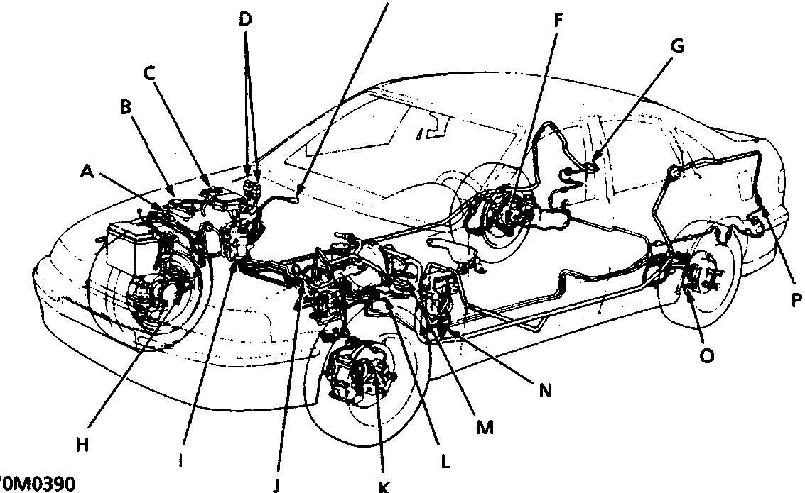
| A | Sensor connector – right front | I | Modulator unit |
| B | Under-bonnet fuse/relay box* | J | Sensor connector – left front |
| C | Under-bonnet fuse/relay box* | K | Wheel sensor – left front |
| D | Fail-safe relays – under fusebox* | L | ABS control unit |
| E | Service check connector – 2P | M | ABS inspection connector – 6P |
| F | Wheel sensor – right rear | N | Under-dash fuse/relay box |
| G | Sensor connector – right rear | O | Wheel sensor – left rear |
| H | Wheel sensor – right front | P | Sensor connector – left rear |
* Refer to BRAKES – ABS for Inspection and Repairs
WARNING: The accumulator contains high pressure nitrogen gas, do not puncture, expose to flame or attempt to disassemble the accumulator or it may explode; severe personal injury may result.
Parts & tools for this job For Rover 600
- TOOLOBD2 scanner with ABSSearch: OBD2 scanner ABS SRS
- TOOLDigital multimeterSearch: automotive digital multimeter
Links open Amazon search results in a new tab. As an Amazon Associate I earn from qualifying purchases.