
Component location (page 2 of 2)
- Make
- Rover
- Model
- 600 Rover 600 Repair Manual - Volumes 1 and 2 - 2nd Edition
- Section
- Information
Brakes – ABS BY4Component location · page 2 of 2
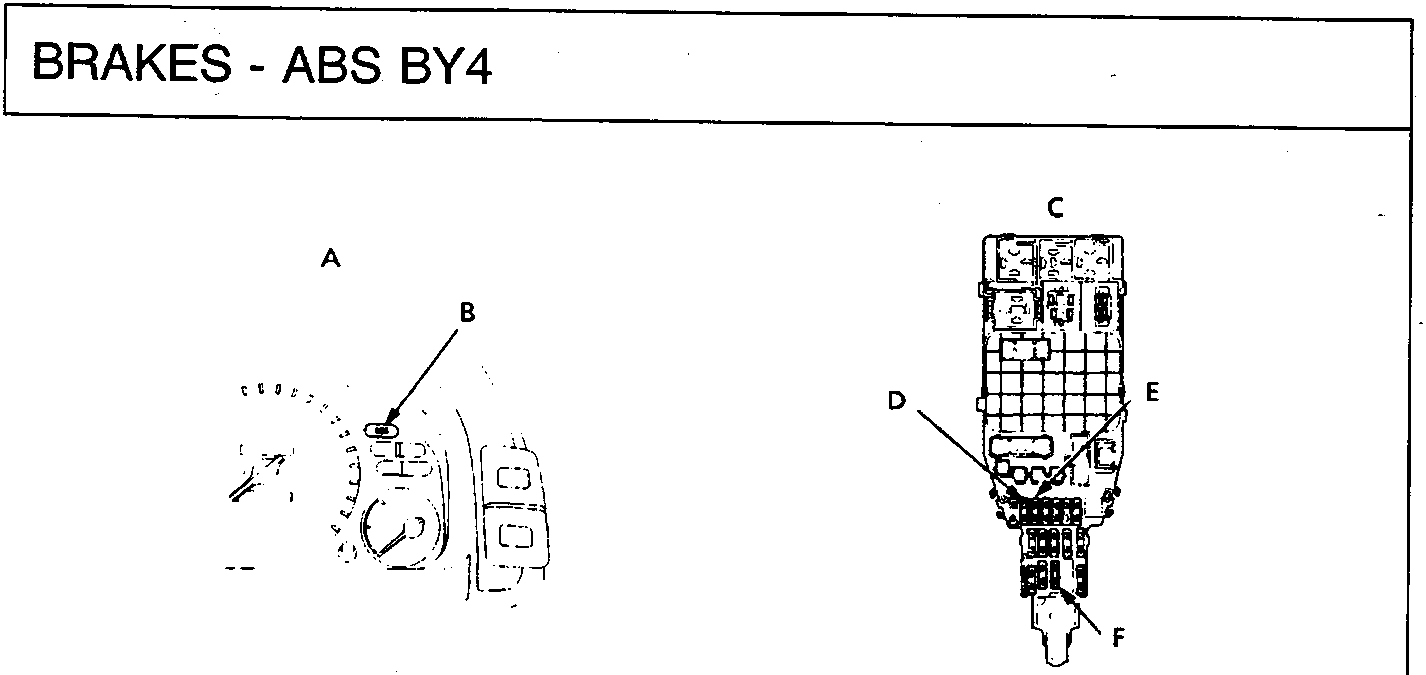
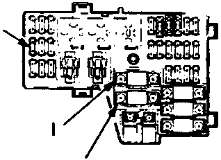
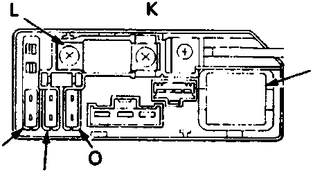
70M0391
| A | Gauge assembly |
| B | ABAS indicator light |
| C | Under – dash fuse/relay box |
| D | Heater control relay/rear defroster relay fuse – 7.5A |
| E | Direction indicator/reversing lights fuse – 10A |
| F | ECU fuse – 15A |
| G | Under – bonnet fuse/relay box |
| H | Stop light/horn fuse – 20A |
| I | Ignition switch fuse – 50A |
| J | Battery fuse – 80A |
| K | Under – bonnet ABS fuse/relay box |
| L | ABS motor fuse – 40A |
| M | Motor check valve fuse – 7.5A |
| N | ABS B2 fuse – 15A |
| O | ABS B1 fuse – 15A |
| P | ABS pump motor relay |
Parts & tools for this job For Rover 600
- TOOLOBD2 scanner with ABSSearch: OBD2 scanner ABS SRS
- TOOLDigital multimeterSearch: automotive digital multimeter
Links open Amazon search results in a new tab. As an Amazon Associate I earn from qualifying purchases.