
Brakes - ABS: information (page 2 of 2)
- Make
- Rover
- Model
- 600 Rover 600 Repair Manual - Volumes 1 and 2 - 2nd Edition
- Section
- Brakes - ABS: information
Brakes and ABSBrakes - ABS: information · page 2 of 2
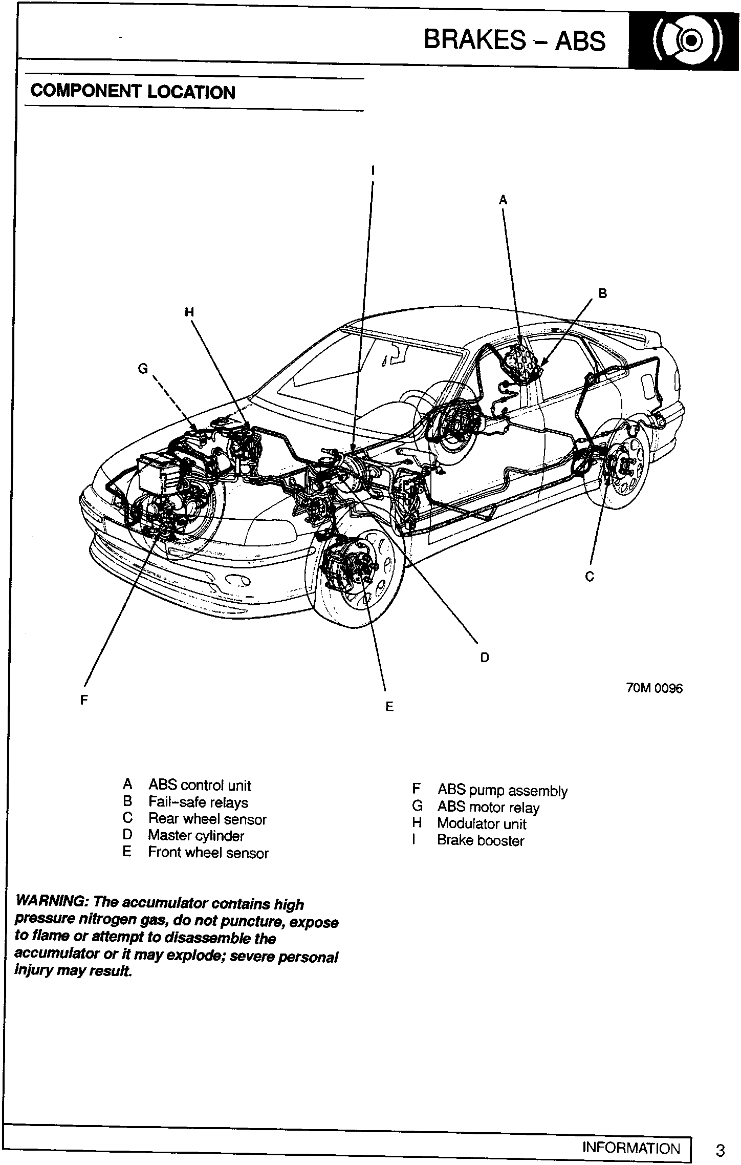
- A ABS control unit
- B Fail-safe relays
- C Rear wheel sensor
- D Master cylinder
- E Front wheel sensor
- F ABS pump assembly
- G ABS motor relay
- H Modulator unit
- I Brake booster
WARNING: The accumulator contains high pressure nitrogen gas, do not puncture, expose to flame or attempt to disassemble the accumulator or it may explode; severe personal injury may result.
Parts & tools for this job For Rover 600
- TOOLOBD2 scanner with ABSSearch: OBD2 scanner ABS SRS
- TOOLDigital multimeterSearch: automotive digital multimeter
Links open Amazon search results in a new tab. As an Amazon Associate I earn from qualifying purchases.