
Cylinder head/valve train: information: Special tools
- Make
- Rover
- Model
- 600 Rover 600 Repair Manual - Volumes 1 and 2 - 2nd Edition
- Section
- Cylinder head/valve train: information › Special tools
EngineSpecial tools
SPECIAL TOOLS
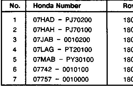
| No. | Honda Number | Rover Number | Description |
|---|---|---|---|
| 1 | 07HAD – PJ70200 | 18G1577 | Valve seal installer |
| 2 | 07HAH – PJ70100 | 18G1581 | Valve guide reamer |
| 3 | 07JAB – 0010200 | 18G1672 | Handle |
| 4 | 07LAG – PT20100 | 18G1671 | Balancer shaft lock pin |
| 5 | 07MAB – PY30100 | 18G1672 – 1 | Pulley holder attachment, 50mm |
| 6 | 07742 – 0010100 | 18G1581 | Valve guide driver |
| 7 | 07757 – 0010000 | 18G1519A | Valve spring compressor |
The tools illustrated in this section are Honda tools, and Rover do not always have an equivalent. Where an equivalent Rover tool is available, it may not be visually identical to the Honda tool.
- Valve seal installer
- Valve guide reamer
- Handle
- Balancer shaft lock pin
- Pulley holder attachment, 50mm
- Valve guide driver
- Valve spring compressor
Parts & tools for this job For Rover 600
- PARTEngine gasket setSearch: Rover 600 engine gasket set
- TOOLTorque wrenchSearch: 3/8 inch torque wrench
- TOOLFeeler gauge setSearch: feeler gauge set
Links open Amazon search results in a new tab. As an Amazon Associate I earn from qualifying purchases.