
Cylinder head/valve train
- Make
- Rover
- Model
- 600 Rover 600 Repair Manual - Volumes 1 and 2 - 2nd Edition
- Section
- Cylinder head/valve train: repairs › Cylinder head/valve train
EngineCylinder head/valve train
CYLINDER HEAD/VALVE TRAIN
Components
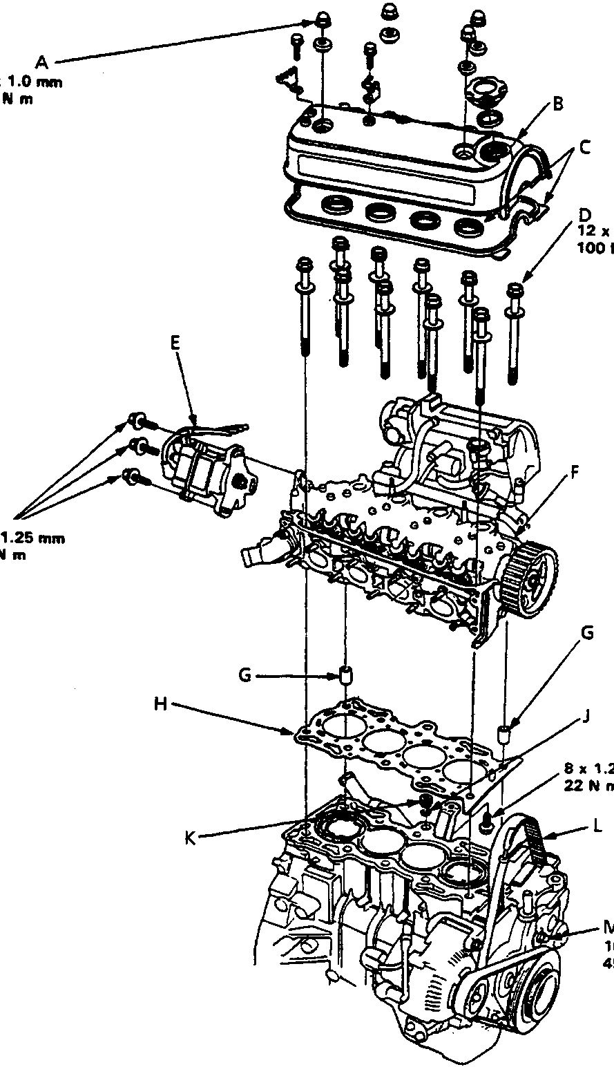
10 N m
100 N m
18 N m
22 N m
45 N m
12M0614
| A | Cap nut |
| B | Cylinder head cover |
| C | Rubber seals |
| D | Cylinder head bolt |
| E | Distributor |
| F | Cylinder head |
| G | Dowel pin |
| H | Cylinder head gasket (metal) |
| J | O-ring |
| K | Oil control orifice |
| L | Timing belt |
| M | Adjusting nut |
Parts & tools for this job For Rover 600
- PARTEngine gasket setSearch: Rover 600 engine gasket set
- TOOLTorque wrenchSearch: 3/8 inch torque wrench
- TOOLFeeler gauge setSearch: feeler gauge set
Links open Amazon search results in a new tab. As an Amazon Associate I earn from qualifying purchases.