
Number 3 piston at TDC:
- Make
- Rover
- Model
- 600 Rover 600 Repair Manual - Volumes 1 and 2 - 2nd Edition
- Section
- Cylinder head/valve train: repairs › Number 3 piston at TDC:
EngineNumber 3 piston at TDC:
Exhaust: 0.30mm +/– 0.03mm
- Loosen locknut and turn adjusting screw until feeler gauge slides back and forth with slight amount of drag.
- Apply engine oil to the locknuts.
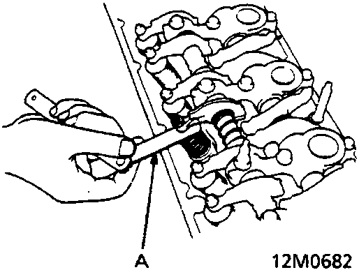
A Feeler gauge
- Tighten locknut and check clearance again. Repeat adjustment if necessary.
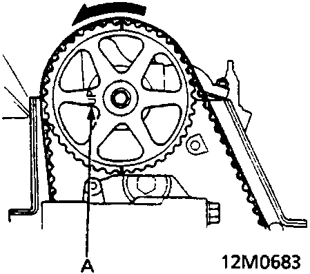
A "UP" mark
Number 3 piston at TDC:
- Rotate crankshaft 180 degrees C anti-clockwise (Camshaft pulley turns 90 degrees). The "UP" mark should be at exhaust side. Adjust the valves on No 3 cylinder.
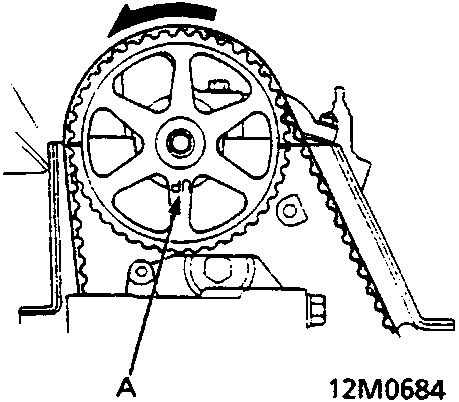
A "UP" mark
Number 4 piston at TDC:
- Rotate crankshaft 180 degrees anti-clockwise to bring No 4 piston to TDC. Both TDC grooves are once again visible. Adjust valves on No 4 cylinder.
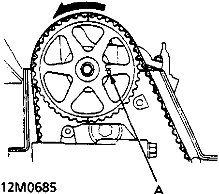
A "UP" mark
Number 2 piston at TDC:
- Rotate crankshaft 180 degrees anti-clockwise to bring No 2 piston to TDC. The "UP" mark should be at intake side. Adjust valves on No 2 cylinder.
Parts & tools for this job For Rover 600
- PARTEngine gasket setSearch: Rover 600 engine gasket set
- TOOLTorque wrenchSearch: 3/8 inch torque wrench
- TOOLFeeler gauge setSearch: feeler gauge set
Links open Amazon search results in a new tab. As an Amazon Associate I earn from qualifying purchases.