Workshop Manuals Factory service & repair Rover
01 Information02 General data03 Engine04 Engine management system – PGM-Fi05 Cooling system, manifold and exhaust06 Clutch07 Manual gearbox08 Automatic gearbox09 Drive shafts10 Differential – manual gearbox11 Differential – automatic gearbox12 Steering13 Suspension14 Brakes and ABS15 Brakes – ABS BY416 Body17 Heating and ventilation18 Electrical19 Supplementary restraint system (SRS)
Rover Rover 600 Repair Manual - Volumes 1 and 2 - 2nd Edition03 · Engine
03 · Engine

Valve clearance

Make
Rover
Model
600 Rover 600 Repair Manual - Volumes 1 and 2 - 2nd Edition
Section
Cylinder head/valve train: repairs › Valve clearance
EngineValve clearance

VALVE CLEARANCE

Adjustment
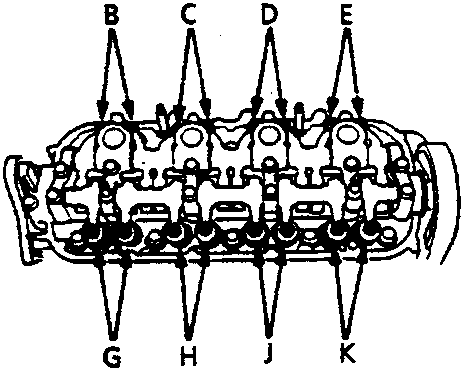
Diagram of cylinder head showing intake and exhaust valve positions labeled A through K, with figure number 12M0679
A INTAKE B No 4 C No 3 D No 2 E No 1 F EXHAUST G No 4 H No 3 J No 2 K No 1
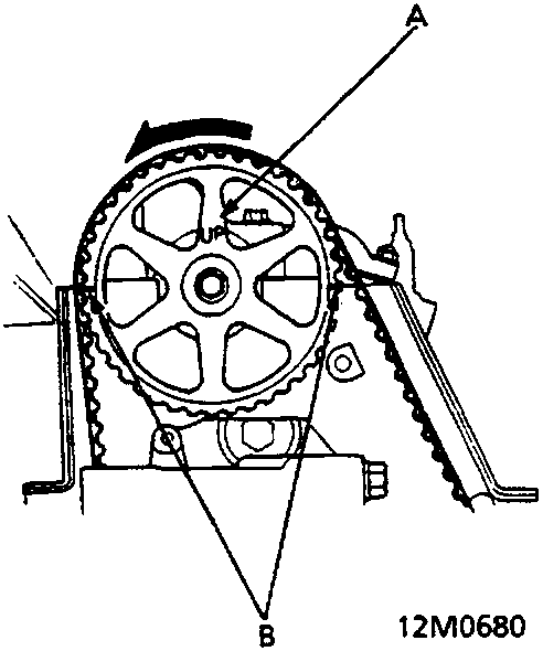
Diagram of camshaft pulley showing UP mark and TDC grooves alignment, with figure number 12M0680
A "UP" mark B TDC grooves Number 1 piston at TDC: 2. Set No 1 piston at TDC. "UP" mark on the camshaft pulley should be at top, and TDC grooves on the camshaft pulley should align with cylinder head surface.

Note:
● Valves should be adjusted cold when the cylinder head temperature is less then 38 degrees C.
● After adjusting, retorque the crankshaft pulley bolt.
1. Remove the cylinder head cover.
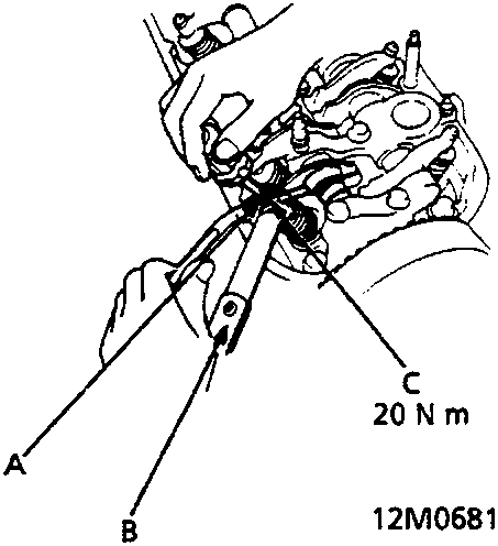
Diagram showing adjustment of valves on No 1 cylinder using an adjusting screw, feeler gauge, and locknut, with figure number 12M0681
A Adjusting screw B Feeler gauge C Locknut 3. Adjust the valves on No 1 cylinder. Intake: 0.26mm +/- 0.03mm

Parts & tools for this job For Rover 600

Links open Amazon search results in a new tab. As an Amazon Associate I earn from qualifying purchases.