
Refit
- Make
- Rover
- Model
- 600 Rover 600 Repair Manual - Volumes 1 and 2 - 2nd Edition
- Section
- Cylinder head/valve train: repairs › Refit
EngineRefit · page 1 of 2
Refit
CAUTION:
- Make sure that all rockers are in alignment with valves when torquing rocker assembly bolts.
- Valve locknuts should be loosened and adjusting screws backed off before installation.
- To prevent rocker arm assembly from coming apart, leave cam holder holding bolts in the holes.
- After wiping down camshaft and journals in cylinder head, lubricate both surfaces and install camshaft.
- Lubricate cam lobes.
- Turn the camshaft until its keyway is facing up (No 1 piston at TDC).
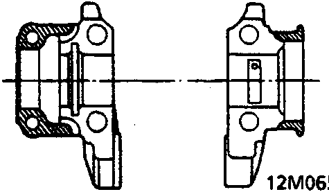
- Apply liquid gasket to the head mating surfaces of the No 1 and the No 6 camshaft holders.
- Apply liquid gasket to the shaded areas.
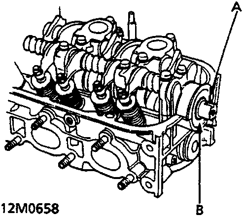
A Camshaft seal
B Seal housing
- Set the rocker arm assembly in place and loosely install the bolts.
Make sure that the rocker arms are properly positioned on the valve stems. - Press in the camshaft seal.
Note: The seal housing surface should be dry. Apply a light coat of oil to camshaft and inner lip of seal.
Original page
Parts & tools for this job For Rover 600
- PARTEngine gasket setSearch: Rover 600 engine gasket set
- TOOLTorque wrenchSearch: 3/8 inch torque wrench
- TOOLFeeler gauge setSearch: feeler gauge set
Links open Amazon search results in a new tab. As an Amazon Associate I earn from qualifying purchases.