
Remove
- Make
- Rover
- Model
- 600 Rover 600 Repair Manual - Volumes 1 and 2 - 2nd Edition
- Section
- Cylinder head/valve train: repairs › Remove
EngineRemove
Remove
Note: Identify valves and valve springs as they are removed so that each item can be reinstalled in its original position.
- Tap each valve stem with a plastic mallet to loosen valve keepers before installing the spring compressor.
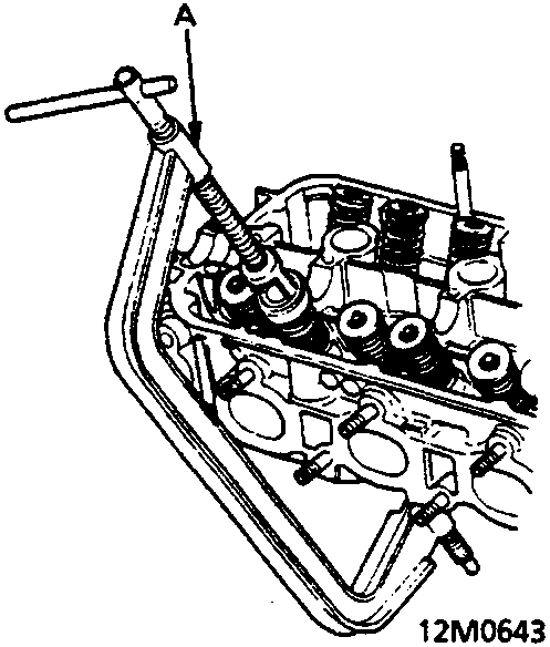
A Valve spring compressor
- Install the spring compressor as shown. Compress the spring and remove the valve keepers.
- Remove the valve guide seal.
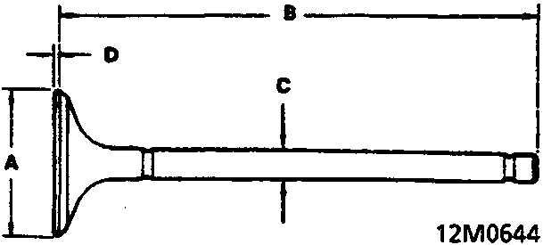
Intake Valve Dimensions:
A Standard (New): 33.90 – 34.10mm
B Standard (New): 110.88 – 111.18mm
C Standard (New): 5.485 – 5.495mm
C Service Limit: 5.455mm
D Standard (New): 0.85 – 1.15mm
D Service Limit: 0.65mm
Exhaust Valve Dimensions:
A Standard (New): 28.90 – 29.10mm
B Standard (new): 122.15 – 122.45mm
C Standard (New): 5.450 – 5.460mm
C Service Limit: 5.420mm
D Standard (New): 1.05 – 1.35mm
D Service Limit: 0.95mm
Parts & tools for this job For Rover 600
- PARTEngine gasket setSearch: Rover 600 engine gasket set
- TOOLTorque wrenchSearch: 3/8 inch torque wrench
- TOOLFeeler gauge setSearch: feeler gauge set
Links open Amazon search results in a new tab. As an Amazon Associate I earn from qualifying purchases.