
Inspection
- Make
- Rover
- Model
- 600 Rover 600 Repair Manual - Volumes 1 and 2 - 2nd Edition
- Section
- Cylinder head/valve train: repairs › Inspection
EngineInspection
Inspection
- Disconnect the alternator terminal and the connector then remove the engine wire harness from the cylinder head cover.
- Remove the cylinder head cover.
- Remove the upper cover.
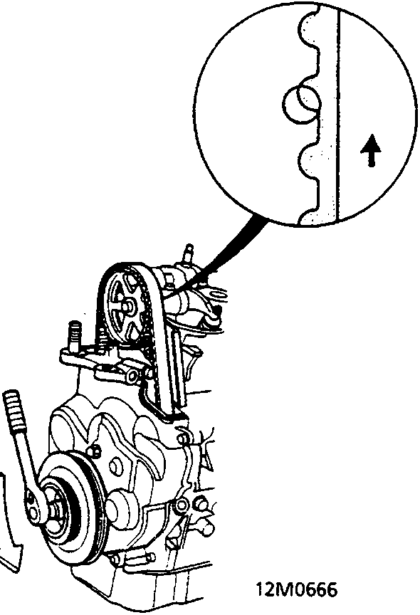
- Rotate the pulley in the direction of the arrow.
- Inspect the timing belt for cracks, oil or coolant soaking and wear of the teeth in the area arrowed.
- Replace the belt if oil or coolant soaked.
- Remove any oil or solvent that gets on the belt or on the pulleys.
- After inspecting, retorque the crankshaft pulley bolt.
Tension Adjustment
CAUTION: Always adjust timing belt tension with the engine cold.
Note:
- The tensioner is spring – loaded to apply proper tension to the belt automatically after making the following adjustment.
- Always rotate the crankshaft anti – clockwise when viewed from the pulley side (as shown by the arrow). Rotating it clockwise may result in improper adjustment of the belt tension.
- Inspect the timing balancer belt before adjusting the belt tension.
- Do not loosen the adjusting nut more than one full turn.
- Disconnect the alternator terminal and the connector, then remove the engine wire harness from the cylinder head cover.
- Remove the cylinder head cover.
- Set the No 1 piston at TDC compression.
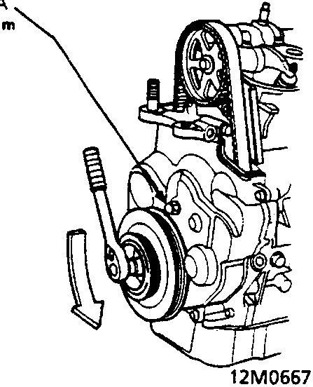
A Adjusting nut
- Loosen the adjusting nut 1 turn, then tighten it.
- Rotate the crankshaft anti – clockwise 3 – teeth on the camshaft pulley, then loosen the adjusting nut to create tension on the timing belt.
- Tighten the adjusting nut.
- After adjusting, retorque the crankshaft pulley bolt.
Parts & tools for this job For Rover 600
- PARTEngine gasket setSearch: Rover 600 engine gasket set
- TOOLTorque wrenchSearch: 3/8 inch torque wrench
- TOOLFeeler gauge setSearch: feeler gauge set
Links open Amazon search results in a new tab. As an Amazon Associate I earn from qualifying purchases.