
Valve Movement
- Make
- Rover
- Model
- 600 Rover 600 Repair Manual - Volumes 1 and 2 - 2nd Edition
- Section
- Cylinder head/valve train: repairs › Valve Movement
EngineValve Movement · page 1 of 2
Valve Movement
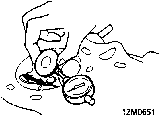
- Position the valve 10mm out of seat as shown.
- Measure the guide – to – stem clearance with a dial indicator while rocking the stem in the direction of normal thrust.
Standard (New): 0.04 – 0.09mm
Service Limit: 0.16mm Exhaust Valve Stem – to – Guide Clearance:
Standard (New): 0.11 – 0.16mm
Service Limit: 0.24mm
- If measurement exceeds the service limit, recheck using a new valve.
- If measurement is now within service limit, reassemble using a new valve.
- If measurement still exceeds limit, recheck using the alternate method, then replace valve and guide, if necessary.
Note: The alternate method of checking guide to stem clearance is to subtract the OD of the valve stem, measured with a micrometer, from the ID of the valve guide, measured with an inside micrometer or ball gauge.
Take the measurements in three places along the valve stem and three places inside the valve guide.
The difference between the largest guide measurement and the smallest stem measurement should not exceed the service limit.
Standard (New): 0.020 – 0.045mm
Service Limit 0.08mm Exhaust Valve Stem – to – Guide Clearance:
Standard (New): 0.055 – 0.080mm
Service Limit: 0.12mm
Refit
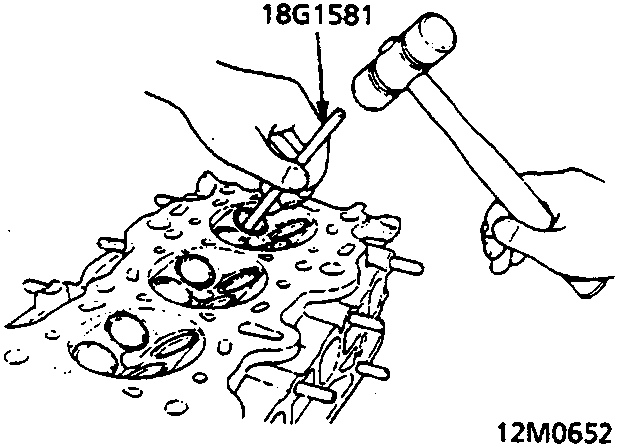
- Heat cylinder head to 150 degrees C before removing or installing guides.
Note:
- It may be necessary to use an air hammer to remove some valve guides.
WARNING: To avoid burns, use heavy gloves when handling heated cylinder head.
- Drive the valve guide out from the bottom of the cylinder head.
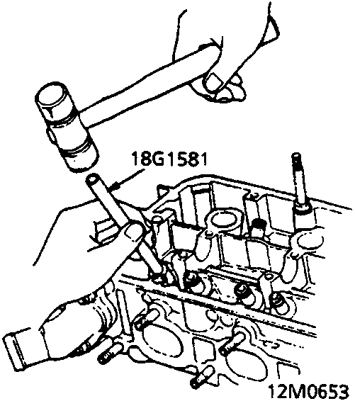
- Drive in a new valve guide to the specified depth.
Parts & tools for this job For Rover 600
- PARTEngine gasket setSearch: Rover 600 engine gasket set
- TOOLTorque wrenchSearch: 3/8 inch torque wrench
- TOOLFeeler gauge setSearch: feeler gauge set
Links open Amazon search results in a new tab. As an Amazon Associate I earn from qualifying purchases.