
Valve Movement (page 2 of 2)
- Make
- Rover
- Model
- 600 Rover 600 Repair Manual - Volumes 1 and 2 - 2nd Edition
- Section
- Cylinder head/valve train: repairs
EngineValve Movement · page 2 of 2
Reaming
Note: For new valve guides only.
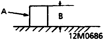
- A Valve guide
- B Valve guide installed height
Valve Guide Installed Height:
Intake: 24.0mm
Exhaust: 15.3mm
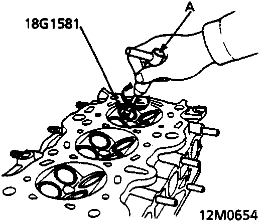
- A Reamer handle
- Coat both reamer and valve guide with cutting oil.
- Rotate the reamer, in a clockwise direction only, the full length of the valve guide bore.
- Continue to rotate the reamer clockwise while removing it from the bore.
- Thoroughly wash the guide in detergent and water to remove any cutting residue.
- Check clearance with a valve.
– Verify that the valve slides in the intake and exhaust valve guides without exerting pressure.
Parts & tools for this job For Rover 600
- PARTEngine gasket setSearch: Rover 600 engine gasket set
- TOOLTorque wrenchSearch: 3/8 inch torque wrench
- TOOLFeeler gauge setSearch: feeler gauge set
Links open Amazon search results in a new tab. As an Amazon Associate I earn from qualifying purchases.