
Cylinder head/valve train (page 2 of 2)
- Make
- Rover
- Model
- 600 Rover 600 Repair Manual - Volumes 1 and 2 - 2nd Edition
- Section
- Cylinder head/valve train: repairs
EngineCylinder head/valve train · page 2 of 2
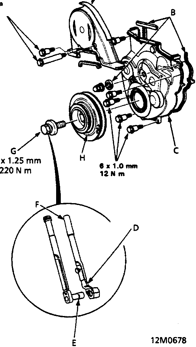
- A Upper cover
- B Rubber seals
- C Lower cover
- D Pulley holder attachment, 50mm
- E Socket wrench, 19mm
- F Handle
- G Pulley bolt
- H Crankshaft pulley
6 x 1.0 mm
12 N m
14 x 1.25 mm
220 N m
6 x 1.0 mm
12 N m
- Remove the 6 x 1.0mm bolt from the timing belt adjuster arm.
- Remove the crankshaft pulley.
- Replace any rubber seals which have been damaged or have deteriorated.
- Install the lower cover.
- Install a rubber seal around the adjusting nut. Do not loosen the nut.
- Install the upper cover.
- Install the crankshaft pulley.
- Coat the threads but not the seating face of the pulley bolt with engine oil. Install and tighten to the specified torque.
Parts & tools for this job For Rover 600
- PARTEngine gasket setSearch: Rover 600 engine gasket set
- TOOLTorque wrenchSearch: 3/8 inch torque wrench
- TOOLFeeler gauge setSearch: feeler gauge set
Links open Amazon search results in a new tab. As an Amazon Associate I earn from qualifying purchases.