
Air intake system schematic
- Make
- Rover
- Model
- Coupé, Cabriolet & Tourer 200/400 Coupé, Cabriolet & Tourer Workshop Manual
- Section
- Description and operation › Air intake system schematic
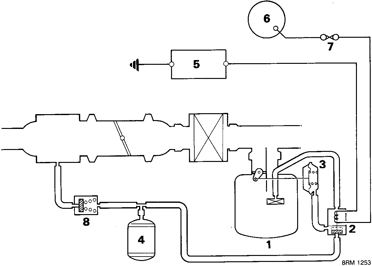
Air intake system schematic
- Two stage resonator
- Resonator control solenoid
- Resonator diaphragm
- Fixed diameter resonator
- E.C.U.
- Ignition switch
- Fuse 14 – 10 amp
- Check valve
Air intake system
Intake air is drawn into the engine via a trunking running adjacent to the radiator. Situated within the intake trunking are two resonators, a small fixed diameter resonator and an E.C.U. controlled two – stage resonator.
Above engine speeds of 3,000 rpm the E.C.U. energises the two – stage resonator control solenoid. Vacuum stored in the reservoir acts on the diaphragm moving the control flap. This increases the resonator aperture lowering intake noise to a minimum.
Intake air is drawn over the electronically controlled resonator and fixed resonator and then passes through a filter which removes all impurities. The filter is located adjacent to the battery.
Idle speed is controlled by the E.C.U. which energises an electronic air control valve (EACV), depending upon inputs from various sensors.
The electronic air control valve system consists of a linear solenoid valve situated in a by – pass passage located in the throttle body. Movement of the solenoid changes idle speed irrespective of throttle valve position. The electronic air control valve (EACV) is controlled by the E.C.U. based on signals received from various sensors.
The E.C.U. activates the solenoid valve to provide optimum engine idle speed.
S.O.H.C. only
During extreme cold conditions, the E.C.U. also energises a fast idle control solenoid valve, which provides the additional air required to obtain a fast idle speed.
The following inputs are required by the E.C.U. for the control of the electronic air control system:
Engine coolant temperature (TW) sensor
Cranking signal
Crank position sensor
Alternator field
Auto position switch
Air conditioner (A/C) compressor
Parts & tools for this job For Rover Coupé, Cabriolet & Tourer
- PARTEngine gasket setSearch: Rover Coupé, Cabriolet & Tourer engine gasket set
- TOOLTorque wrenchSearch: 3/8 inch torque wrench
- TOOLFeeler gauge setSearch: feeler gauge set
Links open Amazon search results in a new tab. As an Amazon Associate I earn from qualifying purchases.