
Fuel system schematic
- Make
- Rover
- Model
- Coupé, Cabriolet & Tourer 200/400 Coupé, Cabriolet & Tourer Workshop Manual
- Section
- Description and operation › Fuel system schematic
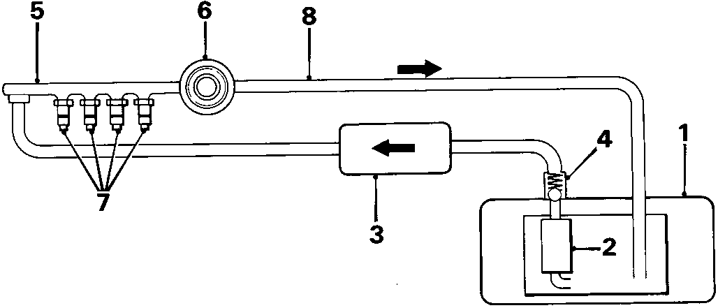
Fuel system schematic
- Fuel tank
- High pressure fuel tank
- Fuel filter
- Pressure regulator solenoid cut – off valve
- Fuel rail
- Pressure regulator
- Fuel injectors
- Return line
Fuel System
The fuel supply system consists of a fuel tank, in – tank high pressure fuel pump, fuel relay, fuel filter, pressure regulator cut – off solenoid valve, injectors and injector resistors.
This system delivers pressure regulated fuel to the injectors and cuts off the fuel delivery when the engine is not running.
Fuel is delivered by the pump to the fuel rail where the fuel pressure is controlled by a pressure regulator valve.
The fuel pressure regulator maintains a constant fuel pressure to the injectors. When the difference between the fuel pressure and the manifold pressure exceeds a predetermined limit, the diaphragm is pushed upwards and the excess fuel is fed back into the fuel tank through the return line.
When the coolant temperature or intake air temperature exceeds a predetermined limit, the pressure regulator cut – off solenoid valve cuts vacuum to the pressure regulator, to ensure high fuel pressure to the injectors and prevent vapour lock.
The fuel rail supplies fuel to the injectors which are operated by the E.C.U.
The injectors are solenoid operated and have a pintle tip enabling fuel to be atomised efficiently. When the E.C.U. completes the earth through the solenoid coil, the valve lifts and pressurised fuel is injected into the intake ports. The injectors are retained by the fuel rail and sealed by an 'O' ring seal at the top and a sealing ring at the bottom. A cushion ring is located between the top of the injector and fuel rail.
Each injector coil is wired in series with a resistor to prevent damage to the injector coils and allow a faster response time. All resistors are contained in a resistor pack located on the L.H. side of the engine compartment bulkhead.
The main fuel relay actually contains two individual relays.
One relay is energised whenever the ignition is on. This supplies the battery voltage to the E.C.U., power to the injectors and power for the second relay.
The second relay energises for two seconds when the ignition is switched on and by the E.C.U. when the engine is running, and supplies power to the fuel pump.
Parts & tools for this job For Rover Coupé, Cabriolet & Tourer
- PARTFuel filterSearch: Rover Coupé, Cabriolet & Tourer fuel filter
- TOOLFuel pressure test kitSearch: fuel pressure test kit
- TOOLFuel line disconnect toolSearch: fuel line disconnect tool
Links open Amazon search results in a new tab. As an Amazon Associate I earn from qualifying purchases.