
Instruments (1.6 model Illustrated): Description and operation
- Make
- Rover
- Model
- Coupé, Cabriolet & Tourer 200/400 Coupé, Cabriolet & Tourer Workshop Manual
- Section
- Description and operation › 1.6 model Illustrated
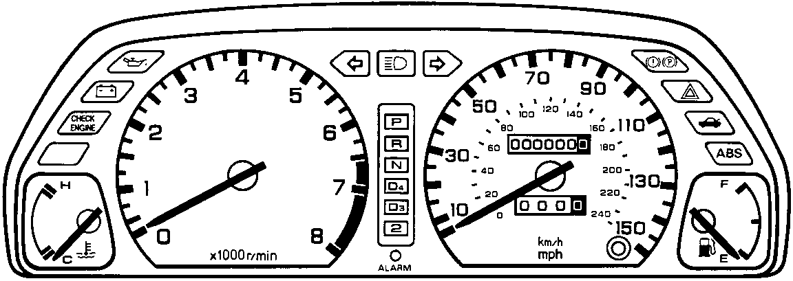
1.6 model Illustrated
INSTRUMENT PANEL
The instrument panel is an electro – mechanical device receiving electrical and mechanical inputs. Electrical signals are received from sender units and are transposed into analogue gauge readouts. Mechanical input is received via a flexible drive from the gearbox.
Instrument panel illumination
There are eight panel illumination bulbs, six for the rear illumination (4x3W & 2x1.4W) and two for front illumination (2x1.4W). They are connected into the sidelight circuit supply from fuse 8, located in the passenger compartment fusebox.
The red/black wire from the fuse is connected into the dimmer switch with the red wire connecting the dimmer circuit to the instrument panel.
Speedometer
The speedometer is driven by a worm gear system from a flexidrive input. The pointer is controlled by an eddy current movement.
A seven digit odometer and a four digit trip distance readout up to 999.9 miles or Km is fitted.
Tachometer
The tachometer signal is taken from the coil to the control board which is secured to the rear of the tachometer sub – assembly. The instrument panel display reading is averaged over all of the engine cylinders to reduce fluctuations due to individual cylinder retardation in spark timing which may occur on engines fitted with programmed ignition systems.
On Diesel models, the tachometer signal is taken from a phase sensing terminal on the alternator.
Fuel gauge
The fuel gauge is driven by an air cored electronic movement which is fluid damped. This type of gauge consists of a pointer mounted on a pivot point with a connection to the movement.
The fuel tank gauge unit comprises a float and is connected to a wirewound resistor which is connected to the fuel gauge and back through the instrument panel to earth. The resistor controls the current flow through to the fuel gauge circuit, which in turn drives the gauge movement against the resistance of the fluid damping. The pivot on which the pointer is mounted is fitted with a return magnet causing the gauge to return to zero when the ignition is switched off.
When the ignition is switched on the fluid damping reduces the movement of the pointer caused by fuel movement in the tank.
When the gauge unit float is at its lowest point, indicating an empty fuel tank, the resistance to earth is at its greatest. The resistance value to fuel gauge position is:
| Sender resistance | Fuel gauge position |
|---|---|
| 105 ohms | Empty |
| 32.5 ohms | Half full |
| 5 ohms | Full |
Parts & tools for this job For Rover Coupé, Cabriolet & Tourer
- TOOLTorque wrenchSearch: 3/8 inch torque wrench
- TOOLSocket setSearch: socket set metric
- BOOKHaynes manualSearch: Haynes manual Rover Coupé, Cabriolet & Tourer
Links open Amazon search results in a new tab. As an Amazon Associate I earn from qualifying purchases.