
Inlet and exhaust manifolds – 1.6 (Manifold and exhaust)
- Make
- Rover
- Model
- Coupé, Cabriolet & Tourer 200/400 Coupé, Cabriolet & Tourer Workshop Manual
- Section
- Description and operation › Inlet and exhaust manifolds – 1.6
Manifold and exhaustInlet and exhaust manifolds – 1.6
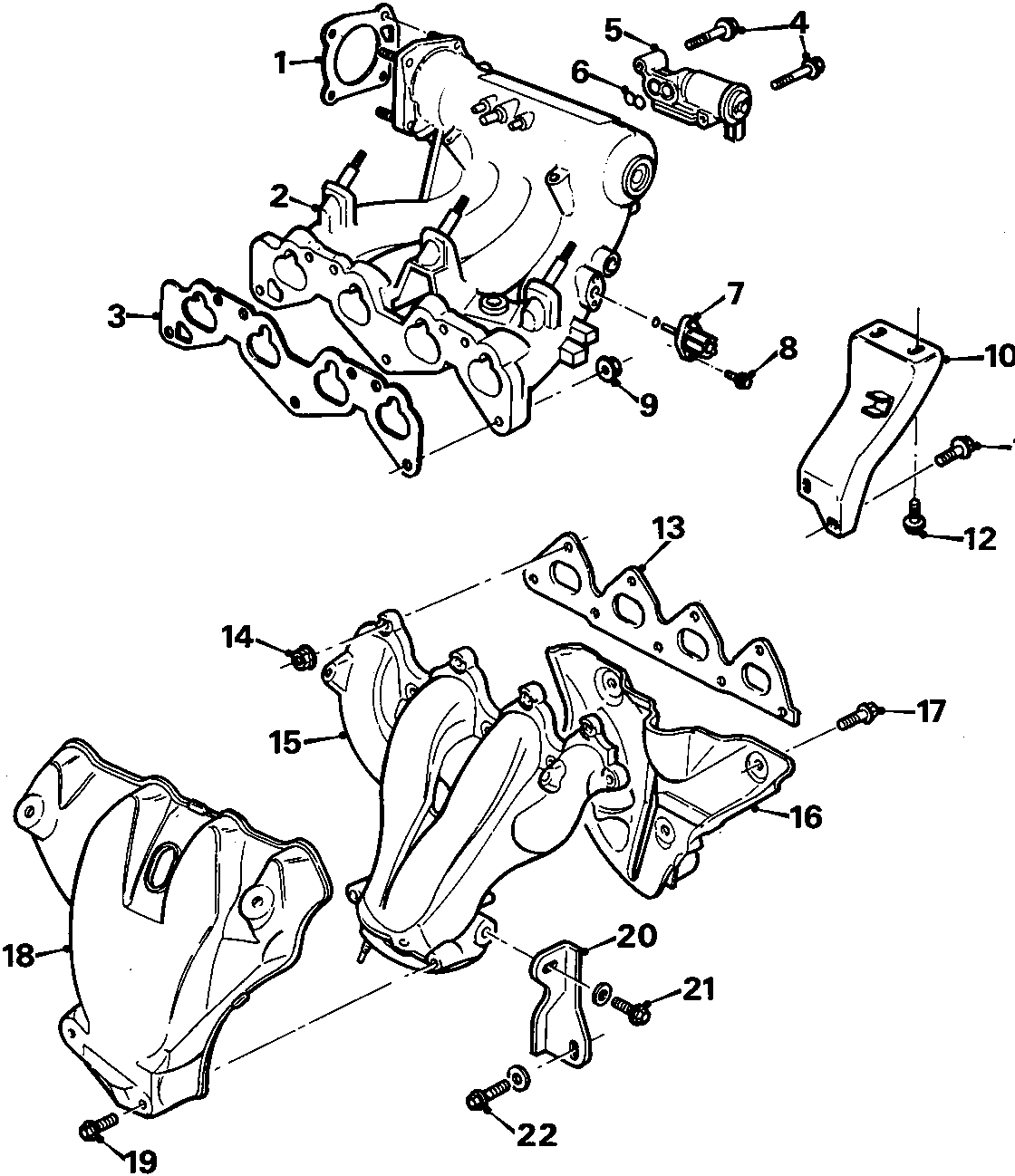
INLET AND EXHAUST MANIFOLDS – 1.6
- Gasket – inlet manifold to throttle body
- Inlet manifold – alloy
- Gasket – manifold to cylinder head
- Bolt – electronic air control valve
- Electronic air control valve
- Seal
- Sensor – temperature
- Bolt – sensor
- Nut – manifold
- Bracket
- Bolt – bracket to block
- Bolt – bracket to manifold
- Gasket manifold to block
- Nut – manifold
- Exhaust manifold
- Heat shield
- Bolt – heat shield
- Heat shield
- Bolt – heat shield
- Bracket
- Bolt – bracket to manifold
- Bolt – bracket to block
Parts & tools for this job For Rover Coupé, Cabriolet & Tourer
- PARTExhaust gasketSearch: Rover Coupé, Cabriolet & Tourer exhaust gasket
- TOOLPenetrating oilSearch: penetrating oil
- TOOLOBD2 scannerSearch: OBD2 scanner
Links open Amazon search results in a new tab. As an Amazon Associate I earn from qualifying purchases.