
Original page
- Make
- Rover
- Model
- Coupé, Cabriolet & Tourer 200/400 Coupé, Cabriolet & Tourer Workshop Manual
- Section
- Contents › Original page
Manual gearbox 1.6Original page
Service Repair No. 54.10.18
Remove
- Raise front of vehicle – L.H. side.
WARNING: Support on safety stands.
- Remove road wheel(s).
- Position drain tin to collect oil spillage from gearbox.
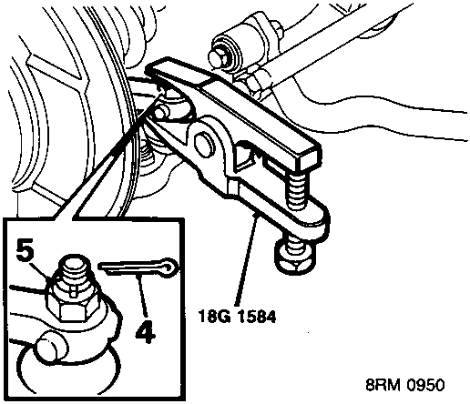
- Remove split pin from steering arm nut.
- Remove steering arm nut.
- Break taper joint using tool 18G 1584.
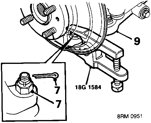
- Remove split pin from lower ball joint nut and remove nut.
- Break taper joint using tool 18G 1584.
- Release lower arm from hub.
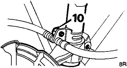
- Remove bolt securing brake hose bracket to damper.
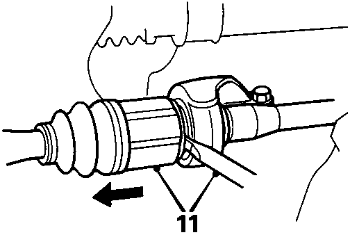
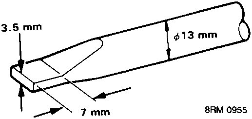
- Using a screwdriver with dimensions as shown, release drive shaft from intermediate shaft.
CAUTION: Pull drive shaft horizontally to avoid damage to intermediate shaft oil seal.
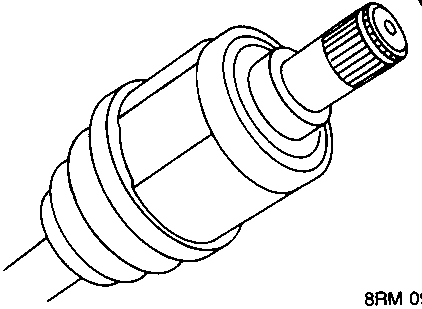
- Remove and discard circlip from drive shaft.
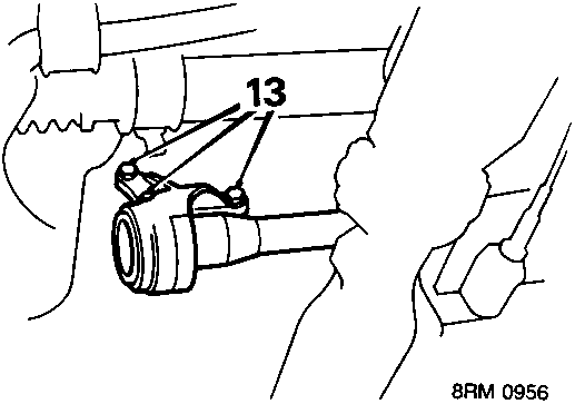
- Remove 3 bolts, intermediate shaft bearing housing to cylinder block.
Original page
Parts & tools for this job For Rover Coupé, Cabriolet & Tourer
- PARTClutch kitSearch: Rover Coupé, Cabriolet & Tourer clutch kit
- TOOLClutch alignment toolSearch: clutch alignment tool
- FLUIDGear oilSearch: Rover Coupé, Cabriolet & Tourer manual gearbox oil
Links open Amazon search results in a new tab. As an Amazon Associate I earn from qualifying purchases.