
Alloy inlet manifold
- Make
- Rover
- Model
- Coupé, Cabriolet & Tourer 200/400 Coupé, Cabriolet & Tourer Workshop Manual
- Section
- Adjustments › Alloy inlet manifold
Modular engine management system - MPiAlloy inlet manifold
Note: Before adjusting cable ensure that cable is correctly routed and located. Do not attempt to adjust throttle cable or engine idle speed by means of the throttle stop screw.
Alloy inlet manifold
- Use Microcheck to ensure that throttle potentiometer and stepper motor are synchronised.
- Switch ignition on, wait 10 seconds and switch ignition off to ensure stepper motor is in setting position.
Alloy and plastic inlet manifold
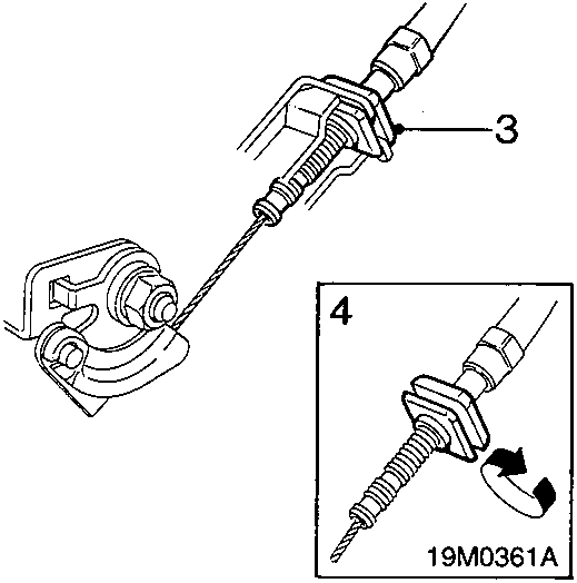
- Release cable adjusting nut from abutment bracket.
- Position outer cable in abutment bracket and adjust cable adjusting nut until it just contacts top of abutment bracket.
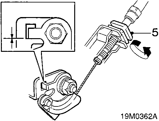
- Alloy inlet manifold: Hold cam in 'throttle closed' position, ensure throttle position screw is in contact with the stepper motor pin. Rotate cable adjusting nut until all slack is taken out of inner cable. Ensure any linkage gap is taken up without opening throttle, see inset.
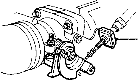
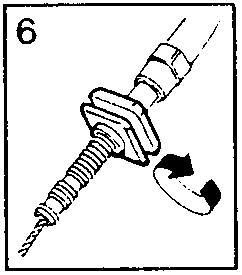
- Plastic inlet manifold: Hold throttle cam in contact with throttle stop screw. Rotate cable adjusting nut until all slack is taken out of inner cable. Ensure throttle does not open.
CAUTION: Ensure all free play is removed from outer cable.
- Locate groove in cable adjusting nut in abutment bracket.
- Operate throttle pedal and ensure that throttle will open to its stop.
Parts & tools for this job For Rover Coupé, Cabriolet & Tourer
- PARTEngine gasket setSearch: Rover Coupé, Cabriolet & Tourer engine gasket set
- TOOLTorque wrenchSearch: 3/8 inch torque wrench
- TOOLFeeler gauge setSearch: feeler gauge set
Links open Amazon search results in a new tab. As an Amazon Associate I earn from qualifying purchases.