
Leon Mk1
|
|
|
|
|
| Assembly chart |
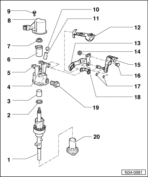
| 1 - | Selection axle |
| 2 - | Stop ring |
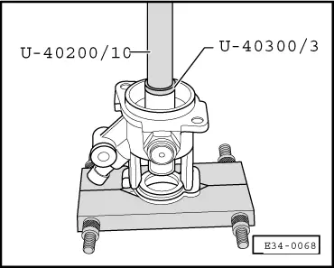
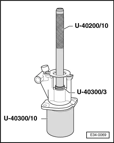
| 3 - | Ball bearning sleeve |
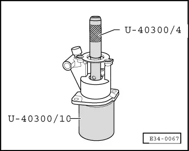
| q | Dismount → Fig. |
| q | Assemble → Fig. |
| 4 - | Seal ring |
| q | Remove by levering with a screwdriver. |
| q | Assemble → Fig. |
| 5 - | Connection top |
| 6 - | Crown |
| q | The bead faces towards the switch for the reverse gear light. |
| q | Apply a fine layer of MoS2 grease onto the bead. |
| 7 - | Hexagonal nut, 25 Nm |
| q | Self-blocking |
| q | Always replace |
| 8 - | Support |
| q | For the reverse gear light switch. |
| 9 - | Bolt |
| 10 - | Top |
| q | Vent top for the gearbox |
| 11 - | Sleeve |
| q | Fit it to the end, if it comes as an individual component |
| 12 - | Selection lever |
| q | Position for assembly: The cog of the gear stick only fits in with the cog of the gear stick in one position. |
| q | It can be changed with the gear stick mounted in the vehicle. |
| q | Position for assembly → Chapter |
| 13 - | Return lever |
| 14 - | Nut, 15 Nm |
| 15 - | Drag part |
| q | With the axle for housing the return lever. |
| q | Position for assembly → Chapter |
| 16 - | Bolt |
| q | Insert it into the drag part. |
| 17 - | O-ring seals |
| q | Assemble them on the axle of the drag parts. |
| 18 - | Separating part |
| q | Insert it on the return lever. |
| 19 - | Bolt for blocking, 40 Nm |
| 20 - | Seal top |
|
|
|
|