
Leon Mk1
| Clutch housing: repairing |
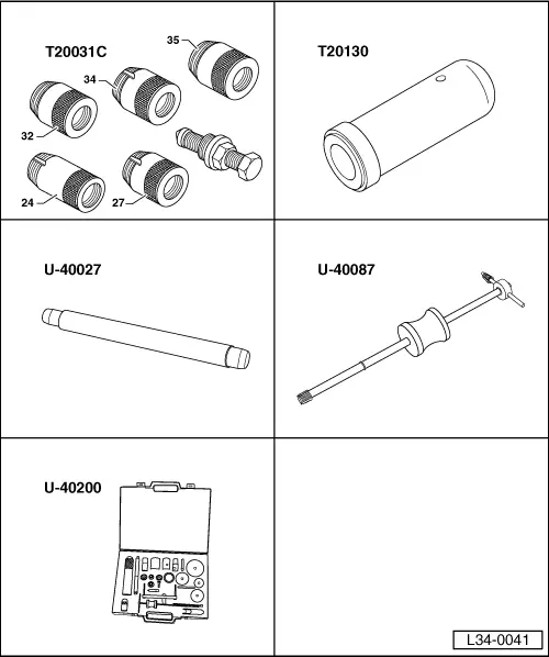
| Special tools and workshop equipment required |
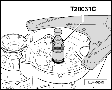
| t | Oil seal extractor (Ø 24 mm) -T20031C- |
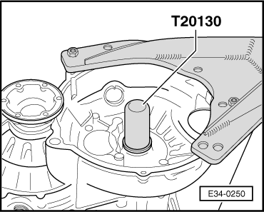
| t | Oilseal fitting tool -T20130- |
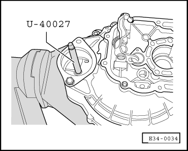
| t | Tool for fitting starter motor bush -U-40027- |
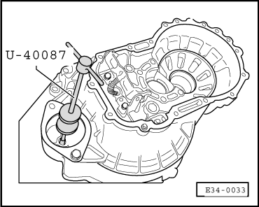
| t | Threaded taps with hammer -U-40087- |
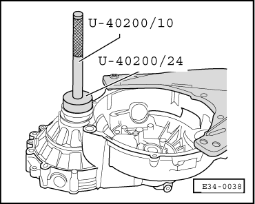
| t | Gearbox repair set -U-40200- |
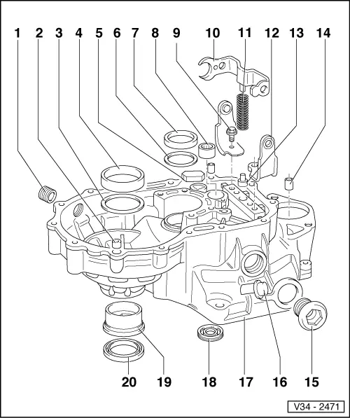
| 1 - | Oil drain screw |
| q | 25 Nm |
| q | Without magnet |
| 2 - | Adjustment sleeve |
| q | 2 units |
| 3 - | Shim S2 |
| q | Always 1 mm thick |
| 4 - | Outer track, roller bearing |
| q | For differential |
| q | Removing and fitting → Chapter |
| q | If replaced, adjust differential → Chapter |
| 5 - | Magnet |
| q | Secured between the gearbox casing and the clutch housing |
| q | Assemble with sealing paste -AMV 188 200 03- |
| 6 - | Shim |
| q | For layshaft |
| q | Adjustment chart → Chapter |
| 7 - | Outer track, roller bearing |
| q | For layshaft |
| q | Removing and fitting → Chapter |
| q | If replaced, adjust layshaft → Chapter |
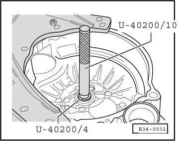
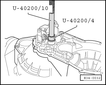
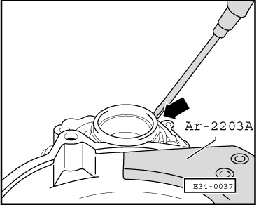
| 8 - | Needle roller bearing |
| q | For input shaft |
| q | Remove → Fig. |
| q | Fit → Fig. |
| 9 - | Hexagon bolt |
| q | 25 Nm |
| q | With locking teeth under the head |
| 10 - | Selection rod |
| 11 - | Spring |
| 12 - | Support for the coupling rod |
| 13 - | Runner |
| 14 - | Starter motor bush |
| q | Remove → Fig. |
| q | Fit → Fig. |
| q | Can be replaced with the gearbox |
| 15 - | Plug |
| q | Green: clutch diameter, 210 mm |
| q | White: clutch diameter, 190 and 200 mm |
 Note!
Note!| Always select the right bolt (e.g. when changing a gearbox or transforming a clutch). |
| Consequences of fitting the wrong bolts: |
| 1. White bolt - |
| 210 mm Ø clutch |
| – | The TDC sender would be destroyed and the flywheel markings damaged. Fragments of the sender would fall into the clutch housing. |
| 2. Green bolt - |
| 190 and 200 mm Ø clutch |
| – | The checker would give no reading or and inexact or changing reading. |
| 16 - | Cover cap |
| 17 - | Clutch housing |
| q | In case of replacement → Chapter, Adjustment chart |
| 18 - | Input shaft oilseal |
| q | Remove → Fig. |
| q | Fit → Fig. |
| 19 - | Bush |
| q | For articulation flange oilseal, → Item |
| q | Remove → Fig. |
| q | Fit → Fig. |
| 20 - | Articulation flange oilseal |
| q | Renew → Chapter, Articulation flange oilseals: removing and installing |
|
|
|
|
|
|
|
|
|
|
|
|
|
|