
Leon Mk1
|
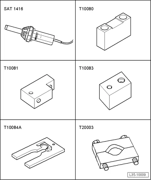
| Special tools and workshop equipment required |
| t | Hot air blower -SAT 1416-, see equivalent → Anchor |
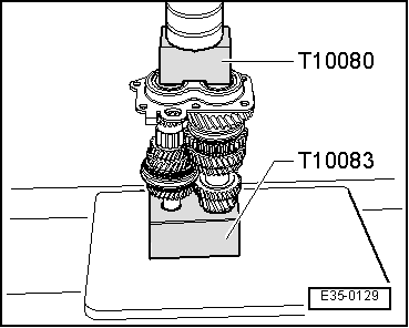
| t | Push rod -T10080-, see equivalent → Anchor |
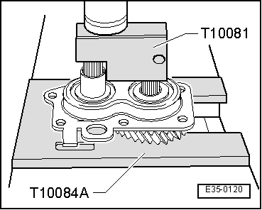
| t | Push rod -T10081-, see equivalent → Anchor |
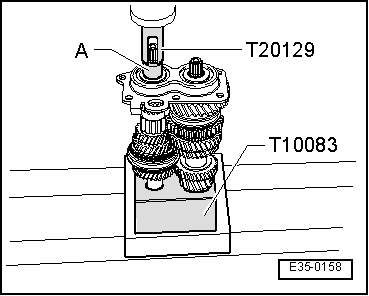
| t | Base -T10083-, see equivalent → Anchor |
| t | Base -T10084A-, see equivalent → Anchor |
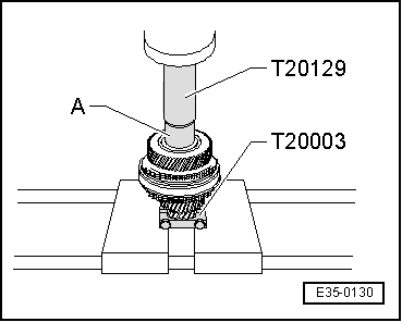
| t | Counterhold -T20003-, see equivalent → Anchor |
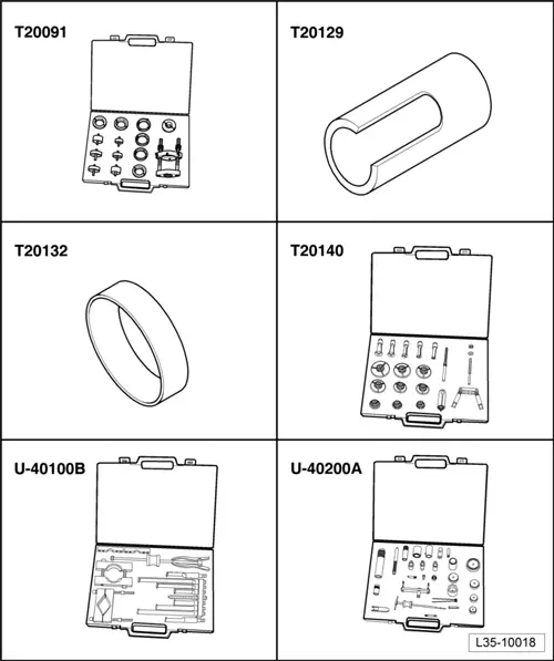
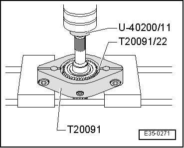
| t | Kit (case) -T20091-, see equivalent → Anchor |
| t | Hose clamp -T20129-, see equivalent → Anchor |
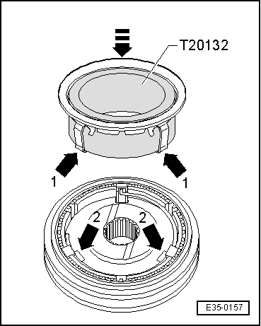
| t | Guide socket -T20132-, see equivalent → Anchor |
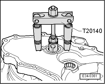
| t | Extractor kit -T20140-, see equivalent → Anchor |
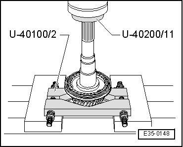
| t | Extractor kit -U 40100B-, see equivalent → Anchor |
| t | Kit (case) -U-40200A-, see equivalent → Anchor |
|
|
|
|
|
|
|
|
 Note
Note
|
|
|
|
 WARNING
|
|
|
|
|
|
|
|
|
|
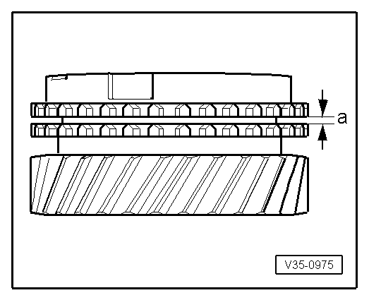
| Distance “to” | Assembly level | Wear limit |
| 3, 4. and 6th gear | 1,1 ... 1.7 mm | 0.5 mm |
|
|
|
|
|
|
|
|
| Measured value (mm) | Thickness of the securing ring (mm) | Axial play (mm) |
| 0,05 ... 0,10 | 2,0 | 0,05 ... 0,15 |
| 0,15 ... 0,20 | 2,1 | 0,05 ... 0,15 |
| 0,25 ... 0,30 | 2,2 | 0,05 ... 0,15 |
| 0,35 ... 0,40 | 2,3 | 0,05 ... 0,15 |
| 0,45 ... 0,50 | 2,4 | 0,05 ... 0,10 |
|
|
|
|
|
|
|
|
|
|
|
|