
Leon Mk1
| Secondary shaft: Assembly overview |
 Note
Note| t | When installing new gears or a secondary input shaft, all details of the → Electronic parts catalogue „ETKA“ and technical data must be observed. |
| t | Install all bearings, synchromeshed gears and synchro-rings on output shaft with gear oil. |
| t | If the synchroniser rings are to be re-used, do not mix up their original positions; fit them to their corresponding mobile pinions. |
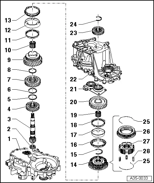
| 1 - | clutch housing |
| 2 - | Cylindrical roller bearing |
| q | With synchro-ring |
| q | Remove → Fig. |
| q | Driving in → Fig. |
| q | Fitting position: once the bearing is fitted, the ring should point towards the secondary shaft |
| 3 - | Output shaft |
| q | Paired with final drive gear wheel. Always renew as a set. |
| q | Check the seating or the inner cylindrical bearing ring for damage or scoring |
| q | If the seating or the inner cylindrical bearing ring shows scoring or damage then replace the secondary shaft and the cylindrical roller bearing |
| 4 - | Gear train for 4th gear |
| q | Fitting position: The collar points towards the 3rd gear → Fig. |
| 5 - | Circlip |
| 6 - | Circlip |
| 7 - | Gear train for 3rd gear |
| q | Fitting position: The collar points towards the 4th gear → Fig. |
| 8 - | Circlip |
| 9 - | 2nd speed selector gear |
| 10 - | Needle bearing |
| q | For 2nd gear |
| 11 - | Inner ring of 2nd gear |
| q | Check for wear → Fig. |
| q | Installation position → Fig. |
| 12 - | Outer ring of 2nd gear |
| q | Place on the inner ring → Item |
| q | Renew if scored |
| q | Installation position → Fig. |
| 13 - | Synchroniser ring for 2nd gear |
| q | Check for wear → Fig. |
| q | Installation position → Fig. |
| 14 - | Locking collar with synchronising hub for 1st and 2nd gear |
| q | After removing the securing ring → Item release the bearing allotment upwards → Fig. |
| q | Dismantling → Fig. |
| q | Assembling the mobile element/synchroniser body → Fig.and → Fig. |
| q | Installation position → Fig. |
| q | Driving in → Fig. |
| 15 - | Circlip |
| q | Pressing out → Fig. |
| q | Driving in → Fig. |
| 16 - | Synchro-ring for 1st gear |
| q | Check for wear → Fig. |
| q | Fit so that the grooves insert in the locking elements of the mobile sleeve → Item |
| 17 - | Outer ring for 1st gear |
| q | Renew if scored |
| q | Insert in synchro-ring → Item. Installation position → Fig.. |
| 18 - | Inner ring for 1st gear |
| q | Check for wear → Fig. |
| q | Check lugs for scoring |
| q | Installation position → Fig. |
| 19 - | Needle bearing |
| q | For 1st gear |
| 20 - | 1st speed selector gear |
| q | Installation position → Fig. |
| 21 - | bearing mounting with grooved ball bearing |
| q | Always replace the bearings with the allotment |
| q | Clean the allotment threaded holes (e.g. with a 6 mm drill bit) |
| q | Pressing out → Fig. |
| q | Pressing in → Anchor |
| 22 - | Gearbox |
| 23 - | 5th gear mobile pinion |
| q | Fitting position: the collar should be orientated towards the gearbox casing cover |
| 24 - | Circlip |
| q | Always replace. |
| q | Determine thickness |
| 25 - | Spring |
| q | Installation position → Fig. |
| 26 - | Mobile element |
| 27 - | Synchro-hub |
| 28 - | Locking keyways |
| q | Quantity: 3 |