
Leon Mk1
| Clutch housing: repairing |
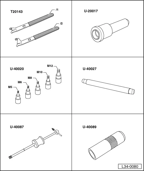
| Special tools and workshop equipment required |
| t | Extractor -T20143- |
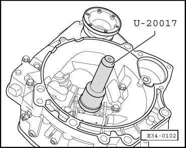
| t | Plunger -U-20017- |
| t | Kit -U-40020- |
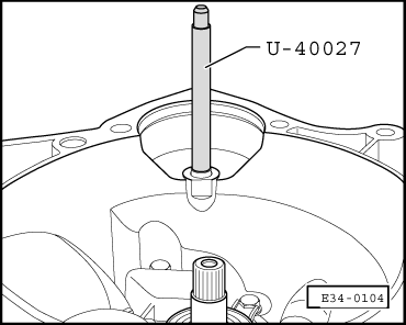
| t | Plunger -U-40027- |
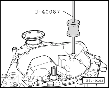
| t | Extractor -U-40087- |
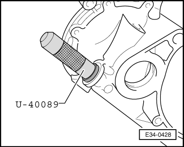
| t | Plunger -U-40089- |
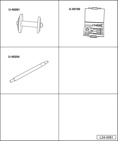
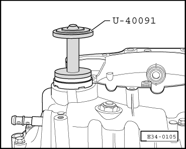
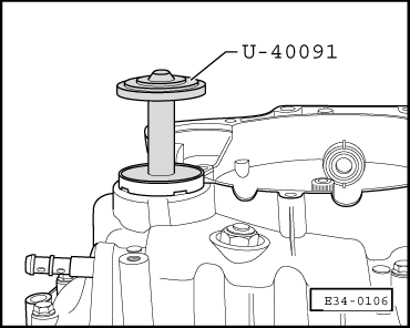
| t | Plunger -U-40091- |
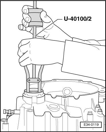
| t | Kit -U-40100- |
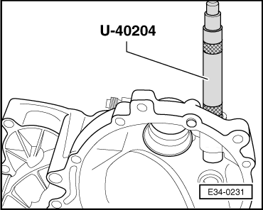
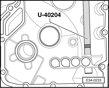
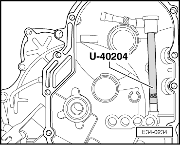
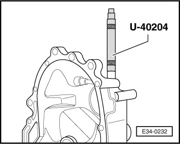
| t | Plunger -U-40204- |
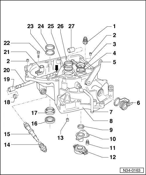
| 1 - | 40 Nm |
| q | For locking the selector rod |
| 2 - | Dowel peg |
| q | 2 units |
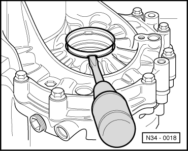
| 3 - | Outer track, roller bearing |
| q | For input shaft |
| q | Removing and installing → Fig. |
| 4 - | Shim |
| q | For input shaft |
| q | Determine thickness → Chapter |
| 5 - | Clutch release lever |
| q | Repair → Chapter |
| 6 - | Plug with cap |
| 7 - | Vent tube |
| 8 - | Clutch housing |
| q | In case of replacement: Adjustment chart → Chapter |
| q | Adjust the selector finger and the control bush → Chapter |
| 9 - | Input shaft oil seal |
| q | Remove → Fig. |
| q | Fitting → Fig. |
| 10 - | Guide bush |
| 11 - | 20 Nm Allen screw |
| q | To secure the guide bush |
| 12 - | Clutch release bearing |
| q | Removing and installing → Chapter |
| 13 - | Starter motor bush-bearing |
| q | Remove → Fig. |
| q | Fitting → Fig. |
| 14 - | Guide bush |
| 15 - | Drive shaft with gear |
| q | For speedometer |
| 16 - | Right-hand flanged shaft oil seal |
| q | Remove → Fig. |
| q | Fitting → Fig. |
| q | Replacement with gearbox in vehicle → Chapter |
| 17 - | Metal bush |
| q | For flanged shaft oil seal, → Item |
| q | Remove → Fig. |
| q | Fitting → Fig. |
| q | Can be replaced with geabox in vehicle |
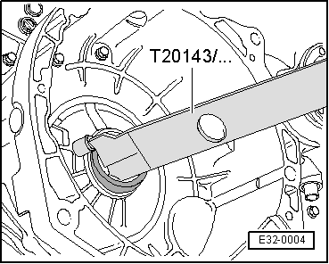
| 18 - | Selector rod oil seal |
| q | Lever it with tool -T20143- to remove |
| q | Fitting → Fig. |
| q | Can be replaced with geabox in vehicle |
| 19 - | Selector rod bush-bearing, front |
| q | Remove → Fig. |
| q | Fitting → Fig. |
| 20 - | Selector rod |
| q | Assembly position: the bevel -arrow- arrow- should be facing the control bush, → Item |
| q | Lubricate contact surfaces with MoS2 grease |
| q | Adjust → Chapter, selector finger and control bush: adjusting |
| 21 - | Control bush |
| q | Adjust → Chapter, selector finger and control bush: adjusting |
| 22 - | 25 Nm Allen screw |
| 23 - | Shim |
| q | For differential |
| q | Determine thickness → Chapter |
| 24 - | Outer roller bearing track |
| q | For differential |
| q | Removing and installing → Chapter |
| q | In case of replacement: → Chapter |
| 25 - | Shim |
| q | For lay shaft |
| q | Determine thickness → Chapter |
| 26 - | Outer roller bearing track |
| q | For layshaft |
| q | Removing and installing → Chapter |
| 27 - | Selector rod bush-bearing, rear |
| q | Remove → Fig. |
| q | Fitting → Fig. |
|
|
|
|
|
|
|
|
 Note!
Note!
|
|
Note!
|
|
Note!
|
|
|
|
|
|
|
|
|
|
|
|