
Leon Mk1
| Secondary shaft: dismounting and assembly |
| t | If new pinions need to be fitted, consult the Identification Initials section, group assignment, reduction ratios, filling amounts → Chapter |
| t | The secondary shaft must always be adjusted whenever components that may affect the position of the tapered roller bearings have been replaced. Consult the Adjustments chart → Chapter. |
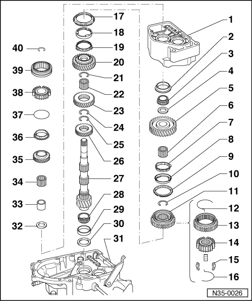
| 1 - | Gearbox casing |
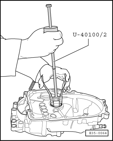
| 2 - | Outer track, tapered roller bearing |
| q | Detachment → Fig. |
| q | Assembly → Fig. |
| 3 - | Tapered roller bearing |
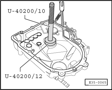
| q | Detach, together with the 1st gear pinion → Fig. |
| q | Assembly: → Fig. |
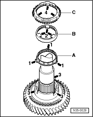
| 4 - | Retainer washer |
| 5 - | 1st gear pinion |
| q | Assembly position → Fig. |
| 6 - | Needle bearing for 1st gear pinion |
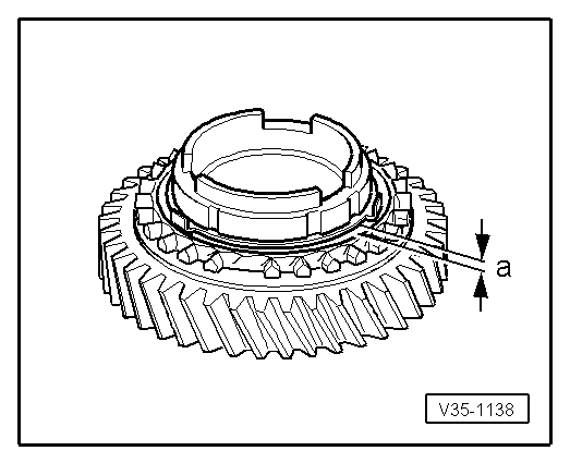
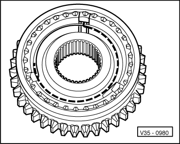
| 7 - | Inner synchroniser ring for 1st gear |
| q | Checking for wear → Fig. |
| q | Check that the flanges show no signs of wear. |
| q | Assembly position → Fig. |
| 8 - | Outer ring for 1st gear |
| q | Attach to the synchroniser ring for 1st gear → Item |
| q | Assembly position → Fig. |
| q | Replace if there are signs of wear or grooves |
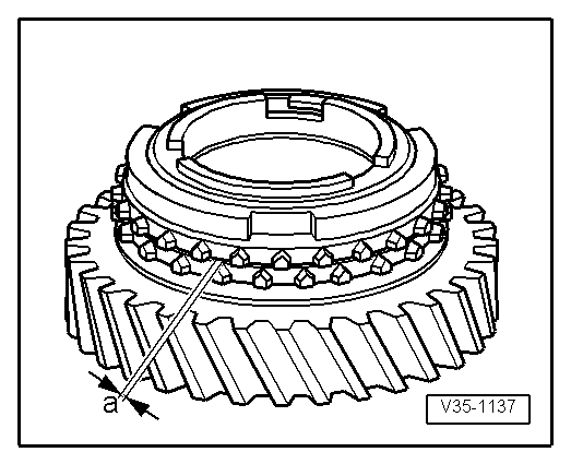
| 9 - | 1st gear synchroniser ring |
| q | Checking for wear → Fig. |
| q | When assembling, the ring flanges must fit into the housings of the 1st and 2nd gear synchroniser unit → Item |
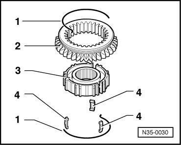
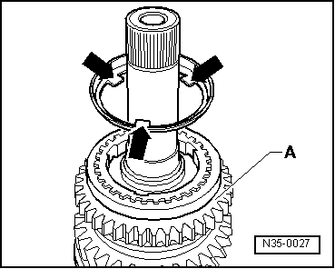
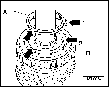
| 10 - | Guard ring |
| q | Detachment → Fig. |
| q | Attachment → Fig. |
| 11 - | Synchroniser unit for 1st and 2nd gears |
| q | The parts go in pairs. |
| q | Detachment → Fig. |
| q | Component assembly → Fig. and → Fig. |
| q | Assembly → Fig. |
| 12 - | Spring |
| 13 - | Sliding sleeve |
| 14 - | Synchroniser bush |
| 15 - | Cotters |
| 16 - | Spring |
| 17 - | 2nd gear synchroniser ring |
| q | Checking for wear → Fig. |
| q | Assembly position → Fig. |
| 18 - | Outer ring for 2nd gear |
| q | Attach to the synchroniser ring → Item |
| q | Assembly position → Fig. |
| q | Replace if there are signs of wear or grooves. |
| 19 - | Inner synchroniser ring for 2nd gear |
| q | Checking for wear → Fig. |
| q | Check that there are no signs of wear on the flanges. |
| q | Assembly position → Fig. |
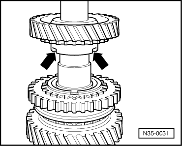
| 20 - | 2nd gear pinion |
| 21 - | Guard ring |
| q | Detachment → Fig. |
| q | Attachment → Fig. |
| 22 - | Needle bearing for 2nd gear pinion |
| 23 - | 3rd gear pinion |
| 24 - | Guard ring |
| q | Detachment → Fig. |
| q | Attachment → Fig. |
| 25 - | Guard ring |
| q | Detachment → Fig. |
| q | Attachment → Fig. |
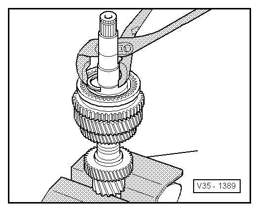
| 26 - | 4th gear pinion |
| q | Assembly position: the identification notch must face the tapered unit. |
| 27 - | Secondary shaft |
| q | If replacing, consult: Adjusting the secondary shaft → Chapter and the Identification Initials section, group assignment, reduction ratios, filling amounts → Chapter. |
| 28 - | Tapered roller bearing |
| q | Removal → Fig. |
| q | Attachment → Fig. |
| 29 - | Outer track, tapered roller bearing |
| q | Removal → Fig. |
| q | Attachment → Fig. |
| 30 - | Adjusting washer |
| q | For the secondary shaft. |
| q | Calculate the thickness → Chapter |
| 31 - | Clutch casing |
| 32 - | Retainer washer |
| q | The washer step should end up facing the tapered roller bearing. |
| 33 - | Needle bearing bush |
| q | Detachment → Anchor |
| q | Assembly → Anchor |
| 34 - | Needle bearing for 5th gear pinion |
| 35 - | 5th gear pinion |
| 36 - | 5th gear synchroniser ring |
| 37 - | Spring |
| q | Fit to the 5th gear synchroniser ring. |
| q | Replace if it shows signs of wear. |
| 38 - | 5th gear synchroniser bush |
| q | Detachment, assembly and adjustment → Chapter onwards |
| 39 - | Sliding sleeve |
| q | Detachment, assembly and adjustment → Chapter onwards |
| 40 - | Guard ring |
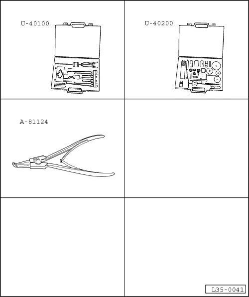
| Special tools and workshop equipment required |
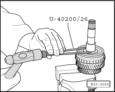
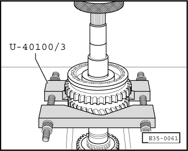
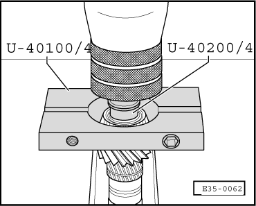
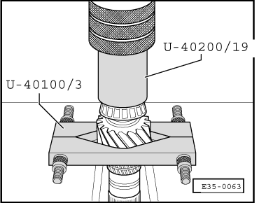
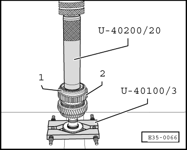
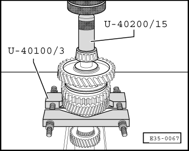
| t | Case for extractor tools for gearboxes -U-40100- |
| t | Replacement parts repair case -U-40200- |
| t | Pliers for opening elastic rings -A-81124- |
|
|
|
|
 Caution
|
|
|
|
|
|
|
|
|
|
 Note!
Note!
|
|
|
|
| Synchroniser ring | Measurement “a” with the new synchroniser | Limit of wear |
| 1st and 2nd gear | 0,75…1,25 mm | 0,3 mm |
|
|
| Synchroniser ring | Measurement “a” with the new synchroniser | Limit of wear |
| 1st and 2nd gear | 1,2…1,8 mm | 0,5 mm |
|
|
|
|
|
|
|
|
|
|
|
|
|
|
|
|