seat Workshop Repair Guides

SEAT Workshop Service and Repair Manuals

Gear selection mechanism, from 03.2009 > < Emergency release of gear selection mechanism from position ?P?
Gear selection mechanism, up to 02.2009: Removing and installing
Consult the equivalence table for tools and equipment according to applicability among Seat / VW / Audi / Skoda → Chapter.
Special tools and workshop equipment required
   
t  Torque wrench kit -SAT 8010-, see equivalent → Anchor
Gear selection mechanism:disassembling
  Note
t  Cleaning norms when working in the gearbox → Chapter.
t  General repair instructions. → Chapter
  Note
All cable clamps that become loose or cut when removing must be re-installed in the same place when installing.
–  Remove engine cover → Booklet101.
–  Remove the air filter body, breather hose and air duct hoses → Rep. gr.24 and → Rep. gr.23 .
–  Removing the gear selector handle → Chapter.
  L00-10226
–  Remove cover -1- above the battery. To do this press the release tab -arrow-.
  WARNING
Take all measures concerning the disconnection of the battery → Electrical system; Rep. gr. 27.
  A27-0190
–  Disconnect battery earth strap-arrow-with the ignition switched off.
  A10-1612
–  Disconnect the connector -C- for the printed circuit board in the cover.
–  Disconnect connector -A- from the gear selection mechanism towards the vehicle set of cables.
  A37-0677
–  Release the selector lever control cable -1- from the selection shaft rod -3-, use, for example a size 10 fixed spanner -2-
–  Remove the control cable from the counter support by pressing the tabs -arrows-.
  A37-0577
–  Release the selector lever control cable from the -1- from the gearbox on the hook -arrow- taking care not to bend the selector lever control cable.
  A37-0581
–  Remove right and left hand side vehicle floor cover -arrows-.
  A10-1663
–  Unscrew the bracket for the exhaust system -arrows- along with the bracket for the lambda probe -1-.
  E37-10006
–  Remove the front tunnel bridge -arrows-.
  A10-1750
–  Release all of the cables from the heat shield -arrows A-.
–  Open the cable clamp -arrow B-.
  A34-0686
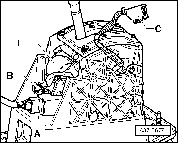
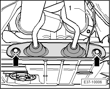
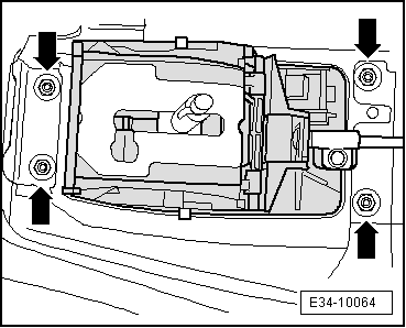
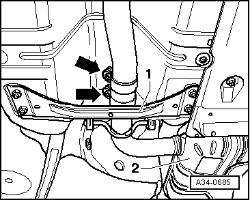
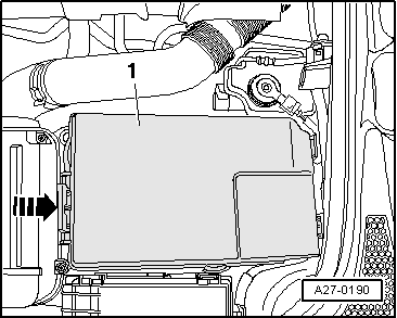
–  Remove the rear tunnel of the bridge -1-.
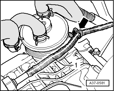
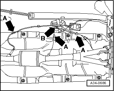
–  Support the front part of the exhaust system, at the level of the catalytic converter, using the hydraulic jack -SAT 1040-.
  Note
The connecting elements of the front exhaust pipe must not be bent more than 30º. Risk of damage!
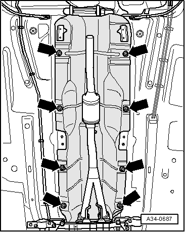
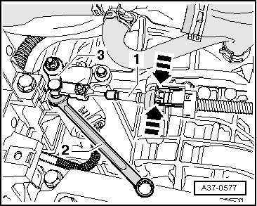
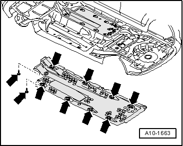
–  Remove the exhaust system by the surrounding sleeve -arrows-.
  Note
A second mechanic is required for removing the rear part of the exhaust system.
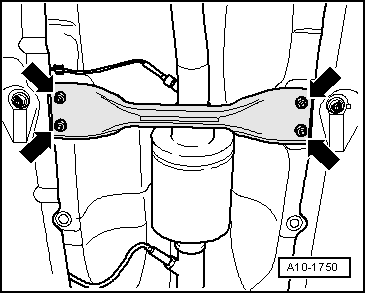
–  Take the rear silencer -2- off mountings and remove the rear part of the exhaust system.
  A34-0685
–  Lower the exhaust system slightly using the hydraulic jack -SAT 1040-. Ensure that there is enough space for the lambda probe cables.
–  Remove the attachments -arrows- and extract the heat shield towards the rear.
  Note
To remove the gear selection mechanism, the help of a second mechanic is required from underneath the vehicle.
  A34-0687
–  Unscrew nuts -arrows-.
–  Remove the gear operation mechanism downwards along with the selector lever control cable taking special care not to bend this cable.
  Note
The gear operation mechanism may also be replaced without the cable; to do this the cable must already be separated from the operation mechanism. Remove the selector lever mechanism → Chapter
Gear mechanism: fitting
Installation is carried out in reverse order, noting the following:
Tightening torques of the nuts and bolts as well as an indication as to they must be renewed or not → Chapter.
–  Carefully insert the gear selector lever cable into the counter support of the gearbox and on the selection shaft rod. While doing this, do not bend the rod of the selection shaft; otherwise the gear changes will not be precise.
–  Do not bend or twist the selector lever cable.
  E34-10064
–  Hang the selector lever cable -1- on the clip -arrow- on the gearbox. When putting tension on the selector lever control cable, keep a distance of at least 5 mm from the ATF cooler.
–  Fit the exhaust system and adjust without putting it under any strain → Engine, mechanics; Rep. gr. 26 .
–  Fit the selector lever handle along with the trimming → Chapter.
–  Take all the necessary precautionary measures when connecting the battery → Electrical system; Rep. gr. 27 .
–  Check operation of ignition key withdrawal lock → Chapter.
–  Adjust selector lever cable → Chapter.
–  Check selector mechanism → Chapter.
  A37-0581

Gear selection mechanism, from 03.2009 > < Emergency release of gear selection mechanism from position ?P?