seat Workshop Repair Guides

SEAT Workshop Service and Repair Manuals

14 pin connector cable harness: removing and fitting > < Removing and installing ATF strainer
Removing and installing the selector housing
Consult the equivalence table for tools and equipment according to applicability among Seat / VW / Audi / Skoda → Chapter.
Special tools and workshop equipment required
t  Torque wrench kit -SAT 8010-, see equivalent → Anchor
t  Protective glasses
  Note
t  The selection unit must always be replaced when faulty or dirty.
t  Rules of cleanliness to be taken into account when working on the automatic gearbox → Chapter.
t  General repair instructions. → Chapter
Removing the selection unit
  WARNING
Take all measures concerning the disconnection of the battery → Electrical system; Rep. gr. 27.
   
–  Remove cover -1- above the battery. To do this press the release tab -arrow-.
  A27-0190
–  Disconnect battery earth strap-arrow-with the ignition switched off.
–  Remove oil pan → Chapter.
–  Remove oil strainer → Chapter.
  A10-1612

–  Make a hand sketch, similar to that in the illustration, representing all of the solenoid valves and their connectors marked with their corresponding colours. Also mark the corresponding conduits with the correct colours.
  Note
t  It is essential, when making this sketch, not to mix up the solenoid valve connectors when refitting the selection unit.
t  Under certain circumstances, mixing up the connectors could cause irreparable damage to the gearbox.
–  Using a small screwdriver, carefully lever off the support feet of the solenoid valve connectors -Position 1 … 8- and separate the connectors.
  Note
If the connectors are damaged, the 14 terminal cable harness or even the selection unit with the solenoid valve must be replaced.
   

–  Unscrew the 3 bolts -D- and -E-.
Unplug or separate the following connectors carefully:
–  Extract the connector -1- on the Automatic gearbox, hydraulic pressure sender -1- -G193 -.
–  Separate the connector-2- to the Gearbox input speed sender - G182 -.
–  Extract the connector -4- on the Automatic gearbox, hydraulic pressure sender -2- -G194 -.
–  Separate the connector -6- to the Gearbox output speed sender - G195 -.
–  Carefully remove the gearbox oil temperature sender - G93--Pos. 8- out of the selector housing along with the bracket -7-.
  Note
When refitting, take into account the bracket attachment on the Gearbox oil temperature sender -G93 -.
–  Unhook the cable harness from the bracket -C-.
  Note
If the connectors have been damaged, replace (depending on the damaged connector) the 8 terminal cable harness, the Gearbox input speed sender -G182- or even the Gearbox output speed sender -G195 -.
   
–  Remove the gear selection lever -A- from the selection shaft.
  Note
t  While doing this, carefully immobilise the gear lever -A- using universal pliers -B-, so that the rotational torque is not transferred to the Multi-function switch -F125 -.
t  Note the slide on the selector housing into which the gear lever is inserted, avoid damage to this.
  A38-0103
–  Unscrew the attachment bolts diagonally -arrows- from the selector gear and remove it carefully.
–  Remove the brackets -1 - and -2 -.
3  - Selector housing designation, in this case, e.g. „A2“
  Note
t  The bolts have different lengths and must be replaced. Take this into account when fitting.
t  Only the securing bolts that are marked are to be removed -arrows-.
t  If other bolts are removed this may cause faults in the selector gear and this may even separate the selector housing.
  A38-0105
t  If necessary, when removing the selector housing ensure that the damper cylinder -E- does not fall or, in this conjunction, remove it along with the two springs.
Install the selector housing
  Note
t  Pay special attention to the layout of the conduits to avoid trapping or damaging them when fitting the selector housing.
t  Damaged or trapped conduits must always be replaced.
  A38-0106
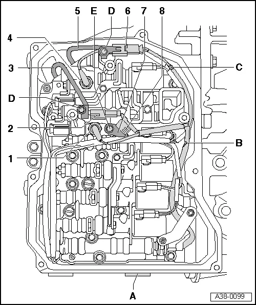
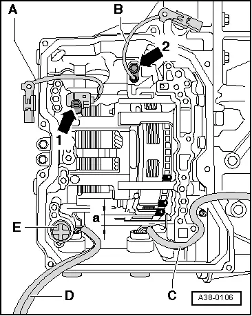
–  Layout the cable harness -C- (with the 8 pin connector) as shown in the illustration, in the curves designed for this in the selector housing.
l  The cable harness -C- should not come into contact with the planetary gears. The free space -a- must be preserved so that the cable harness is not grazed while driving.
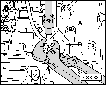
–  Layout the cable harnesses -A-, -B- and -D-, as shown in the illustration, over the edge of the gearbox.
–  Ensure that the damper cylinder -E- is fitted in the gearbox in the position shown by the illustration.
  Note
t  If the damper cylinder -E- has been removed, it must be cleaned along with the two springs and fitted in a similar fashion → Item, → Item, → Item.
t  To do this, the springs must be inserted into each other; smear the outer wall of the damper cylinder and the opening in the gearbox with ATF and then insert all parts into the gearbox.
t  If necessary, keep the damper cylinder pressed into the gearbox (so it does not fall out) until the selector gear has been secured.
  A38-0106
–  Fit the selector housing without applying force.
l  The selector housing must not trap the cable harnesses; trapped cable harnesses must always be replaced.
–  All of the attachment bolts for the selector housing must be replaced.
–  Tighten the cable harness bracket -1- and -2- by hand using the corresponding bolts.
–  Tighten by hand the remaining bolts of the selector housing -arrows-.
–  Take into account the length of the screws:
Arrow - bolt M6 x 21
Arrow A - bolt M6 x 16
Arrow B - bolt M6 x 28
  A38-0105

  Note
t  If the cable -3- (to the Gearbox input speed sender - G182 -) is too short to screw in the connector -2- in the designated place on the valve body, it has not been laid out correctly or it has been trapped by the selection box. The selector housing must be removed once more and the cable must be routed correctly.
t  All conduits that have been trapped must be replaced.
–  Ensure that no conduits have been trapped.
   
–  Next, tighten the bolts -arrows- of the selector housing, from the outside to the inside, to the final torque → Anchor.
  A38-0105
–  Hook the cable harness on the bracket -B-.
–  Insert the gear selection lever -2- on the selection shaft -5-.
  Note
Ensure, while doing this, that the gear lever pin -2- inserts in the slide -1--arrow- If necessary, the slide must be moved towards the interior or exterior of the selector housing.
–  Fit the washer -4- and the nut -3- on the selection shaft.
  Note
t  When doing this, the centring collar of the nut should face the washer and move towards this when the nut is tightened.
t  The cable harness must be laid out under the gear lever.
  A38-0104
–  Tighten the nut to 10 Nm.
  Note
t  While doing this, carefully immobilise the gear lever -A- using universal pliers -B-, so that the rotational torque is not transferred to the Multi-function switch -F125 -.
t  Note the slide on the selector housing into which the gear lever is inserted, avoid damage to this.
  A38-0103

–  Connect the connectors -1 ... 8- on the solenoid valves according to the sketch made earlier. It is absolutely essential to respect the connector and cable colours.
–  Layout the cable harness -B- as shown in the illustration.
  Note
Under certain circumstances, mixing up the connectors could cause irreparable damage to the gearbox.
   

–  Plug in connector -2-.
–  Plug in connector -6-.
  Note
The counter parts of the connectors should have the same colour of the connectors.
–  Insert the bracket -7- on the Gearbox oil temperature sender - G93 --Position 8-.
–  Insert the Gearbox oil temperature sender -G93- along with the support on the gearbox housing and tighten the bolt (M6) -E- to 11 Nm.
–  Insert the connectors -1- and -5-, straight, in the pressure senders.
–  Secure the connectors -2- and -6- on the selector housing with the bolts M5 -Position D- and tighten to 7 Nm.
  Note
t  If the cable -3- (to the Gearbox input speed sender - G182 -) is too short to screw in the connector -2- in the designated place on the valve body, it has not been laid out correctly or it has been trapped by the selection box. The selector housing must be removed once more and the cable must be routed correctly.
t  All conduits that have been trapped must be replaced.
–  Secure the cable harness -B- on the bracket -C- and lay it out in a similar manner to that shown in the illustration.
–  Fit the oil strainer → Chapter.
–  Install oil pan → .
–  Take all the necessary precautionary measures when connecting the battery → Electrical system; Rep. gr. 27.
–  Fill with ATF, check and correct ATF level → Chapter.
Tightening torques
   
ComponentNm
Selection unit to the gearbox housing (from outside to inside)
Bolts M6; take into account the different lengths of bolt
8 + 90° → Remark → Remark
Gear lever to the selection shaft (nut)10
Gearbox oil temperature sender -G93-
(M6 screw with the bracket on the selector housing)
11
2 connectors for the speed senders
(M5 screw on the selector housing)
7

1)  Renew bolts
2)  90º is equivalent to a quarter turn.
   

14 pin connector cable harness: removing and fitting > < Removing and installing ATF strainer