seat Workshop Repair Guides

SEAT Workshop Service and Repair Manuals

Input shaft: > < Secondary shaft for 1st to 4th gear: Assemble in gearboxes manufactured from week 44/09 to 22/10
Secondary shaft for 1st to 4th gear: Assemble gearboxes manufactured from week 22/10
   
Check the inner friction surface of the 1st, 2nd and 3rd gear for wear
–  Press in the inner ring -A- for the cone of the pinion gear.
–  Press outer ring -2- on cone of inner ring. Measure the clearance gap at 3 points -a- offset by approx. 120° using a feeler gauge.
–  Make a note of average value.
  S35-0371
Wear limit, dimension -a-
1. st gear, 2nd gear and 3rd gear0.4 mm

   
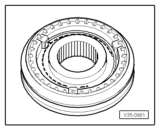
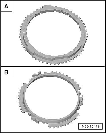
Check the outer friction surface of the 1st, 2nd and 3rd gear for wear
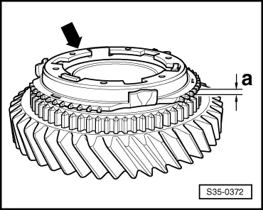
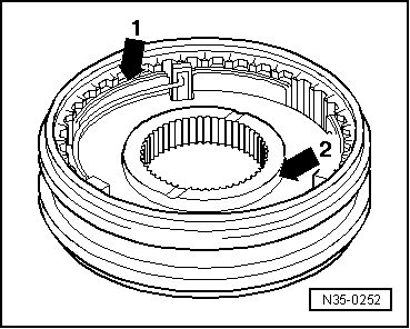
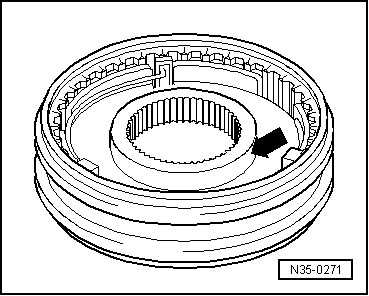
–  Check the synchro ring -arrow- on the tyre on the inner friction surface or for an axial indication of wear, replace if necessary.
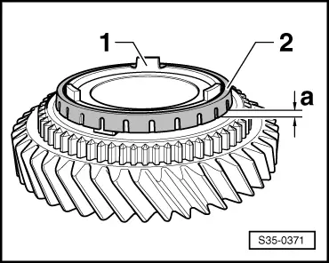
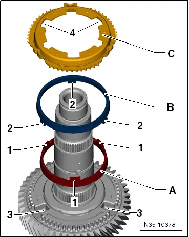
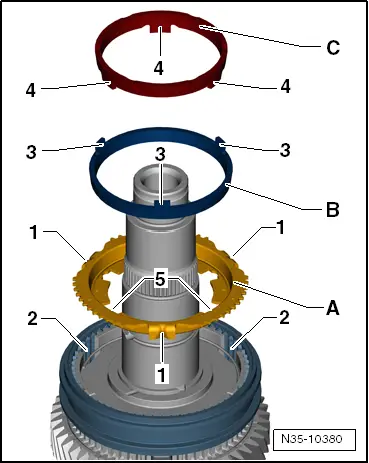
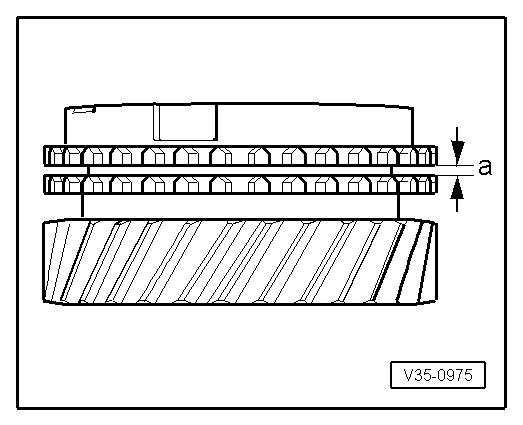
–  Fit the inner ring, outer ring and the synchro-ring on the cone of the inner ring.
–  Press the synchro-ring against the outer ring and turn them both to achieve the correct seating.
–  Measure the clearance gap at 3 points -a- offset by approx. 120° using a feeler gauge.
–  Make a note of average value.
  S35-0372
Wear limit, dimension -a-
1. st gear, 2nd gear and 3rd gear0.8 mm

–  Install synchromeshed gear for 2nd gear with needle bearing.
   
Installation of outer ring, inner ring and synchro-ring for 2nd gear
–  Fit the interior ring -A- onto the mobile pinion.
The lugs -1- must point in the opposite direction of the mobile pinion.
–  Fit the outer ring -B-.
The lugs -2- engage in the recesses -3- of the mobile pinion.
–  Fit the synchroniser ring -C-.
The larger recesses -4- engage in the tabs -1- of the inner rings -A-.
  N35-10378
Disassemble and assemble the mobile element and synchroniser body for the 1st and 2nd as well as 3rd and 4th gears
1 - Elastic ring
2 - Locking piece
3 - Mobile element
4 - Synchro-hub
–  Slide locking collar over synchro-hub.
With 3rd and 4th gear, the width of the synchroniser body collar and, if applicable, the edge reinforcement to the mobile element point in the same direction.
The recesses of the synchromesh assembly and mobile element must lie over another for the locking elements.
  V35-1142
Assemble the mobile element and synchroniser body for the 1st and 2nd as well as 3rd and 4th gears
The mobile element is on the synchromesh body.
–  Insert locking pieces and install springs offset 120°. Angled end of spring must locate in hollow locking piece.
  V35-0981
Installation position of locking collar with synchro-hub for 1st and 2nd gears
The groove -arrow 1- and the tight collar -arrow 2- of the synchroniser body should point to the 1st gear.
  N35-0252
Pressing on locking collar and synchro-hub for 1st and 2nd gears
The lugs -A- of the synchro-rings engage in the recesses -B- of the synchroniser body.
–  Install retaining ring.
  N35-10379
Installation of the synchro-ring, outer ring and inner ring for 1st gear
–  Fit the synchroniser ring -B- to the synchroniser body.
Lugs -1- engage in notches -2- of synchro-hub.
–  Position the outer ring -B- on the synchro-ring.
The lugs -3- must point in the opposite direction of the synchro-ring.
–  Mount the inner ring -C- on the outer ring.
Lugs -4- engage in larger notches -5- of synchro-ring -A-.
  N35-10380
Move the mobile pinion of 1st gear with needle bearing.
l  The lugs -arrow A- of synchro-ring -1- are located in the recesses of the synchroniser body -2-.
The tabs -arrows B- of the outer rings engage in the recesses -arrows C- of the mobile pinion -3-.
–  Install thrust washers for 1st and 4th gears → Item and → Item.
–  Install the mobile pinion for 4th gear with the needle bearing.
  S35-0367
Check 4th gear synchroniser ring for wear.
  N35-10479
-A- = Synchro-ring made of brass
Dimension -a-Installation dimensionWear limit
4. gear1.0 ... 1.7 mm0.5 mm

   
-B- = Synchro-ring made of steel
Dimension -a-Installation dimensionWear limit
4. gear1.3 ... 2.4 mm0.8 mm

   
–  Press the synchroniser ring against the mobile pinion cone and measure the distance -a- with a thickness gauge.
  V35-0975
Installation position of locking collar with synchro-hub for 3rd and 4th gears
The wider shoulder of the synchronising hub -arrow- must face towards 3rd gear.
–  Place the 4th gear synchro-ring on the 4th speed selector gear.
  N35-0271
Drive in the mobile element / synchro-hub for 3rd and 4th gear
–  Turn synchro-ring so that grooves align with locking pieces.
–  Install retaining ring.
  N35-0248
Installation of synchro-ring outer ring and 3rd gear inner ring
–  Fit the synchroniser ring -B- to the synchroniser body.
Lugs -1- engage in notches -2- of synchro-hub.
–  Position the outer ring -B- on the synchro-ring.
The lugs -3- must point in the opposite direction of the synchro-ring.
–  Mount the inner ring -C- on the outer ring.
Lugs -4- engage in larger notches -5- of synchro-ring -A-.
  N35-10380
Move the mobile pinion of 3rd gear with needle bearing.
l  The lugs -arrow A- of synchro-ring -1- are located in the recesses of the synchroniser body -2-.
The tabs -arrows B- of the outer rings engage in the recesses -arrows C- of the mobile pinion -3-.
–  Move the mobile pinion of 3rd gear with needle bearing.
  Note
t  Press on tapered roller bearing inner race → Fig..
t  Determine retaining ring for tapered roller bearing inner race → Fig..
  S35-0367

Input shaft: > < Secondary shaft for 1st to 4th gear: Assemble in gearboxes manufactured from week 44/09 to 22/10