
Leon Mk1
|
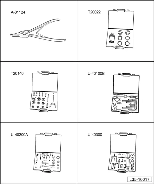
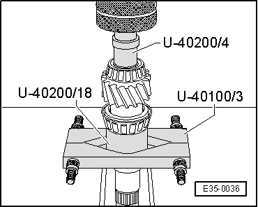
| Special tools and workshop equipment required |
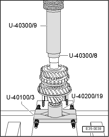
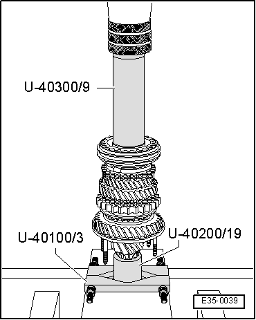
| t | Base -A-81124-, see equivalent → Anchor |
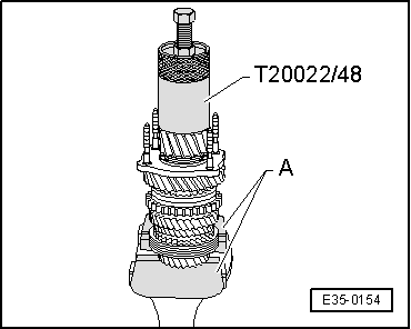
| t | Kit (case) -T20022-, see equivalent → Anchor |
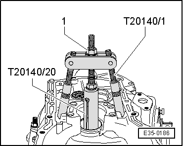
| t | Extractor kit -T20140-, see equivalent → Anchor |
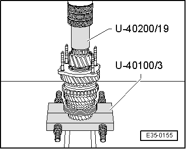
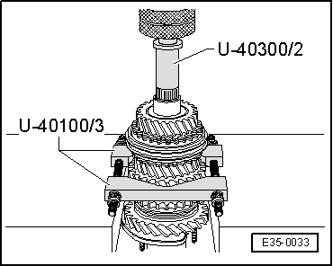
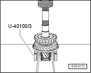
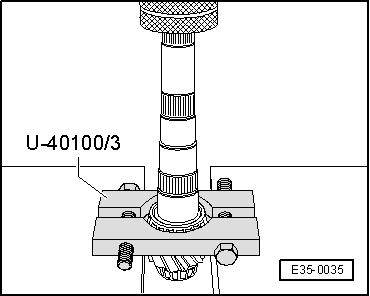
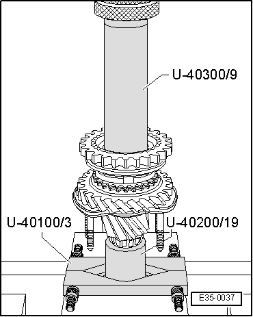
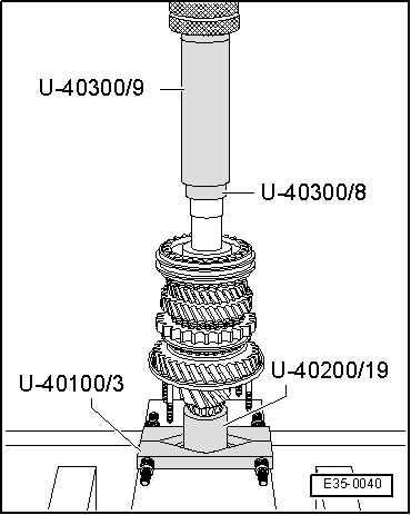
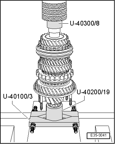
| t | Extractor kit -U 40100B-, see equivalent → Anchor |
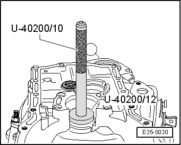
| t | Kit (case) -U 40200A-, see equivalent → Anchor |
| t | Kit (case) -U 40300-, see equivalent → Anchor |
|
|
|
|
|
|
|
|
|
|
|
|
|
|
 Note
Note
|
|
|
|
|
|
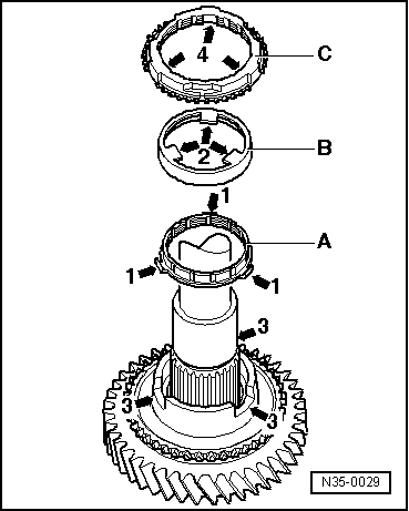
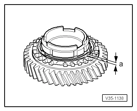
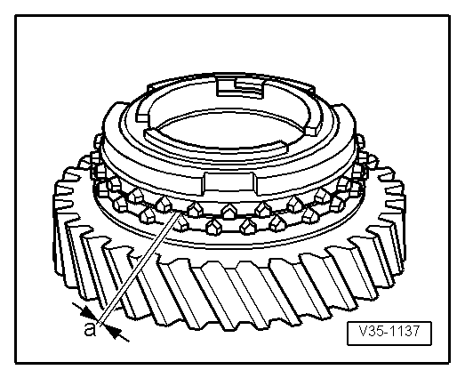
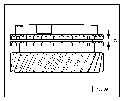
| Synchro-ring | Measurement „a“ in new synchro | Wear limit |
| 1st and 2nd gears | 0.75...1.25 mm | 0.3 mm |
|
|
| Synchro-ring | Measurement „a“ in new synchro | Wear limit |
| 1st and 2nd gears | 1.2 ... 1.8 mm | 0.5 mm |
|
|
|
|
|
|
|
|
|
|
|
|
|
|
|
|
|
|
|
|
| Synchro-ring | Measurement „a“ in new synchro | Wear limit |
| 1st gear | ||
| 3rd gear | 1.0 ... 1.7 mm | 0.5 mm |
| 4. gear |
|
|
|
|
|
|
|
|
|
|
|
|
|
|
|
|