seat Workshop Repair Guides

SEAT Workshop Service and Repair Manuals

Installing gearbox > < Gearbox?: removing and fitting
Removing gearbox
Removing gearbox
Consult the equivalence table for tools and equipment according to applicability among Seat / VW / Audi / Skoda → Chapter.
   
Special tools and workshop equipment required
t  Hydraulic jack -SAT 1040-, see equivalent → Anchor
t  Torque wrench kit -SAT 8010-, see equivalent → Anchor
t  Gearbox support -T20138C -, see equivalent → Anchor
t  Base -T20145-
t  Socket -U 30025E -, see equivalent → Anchor

t  
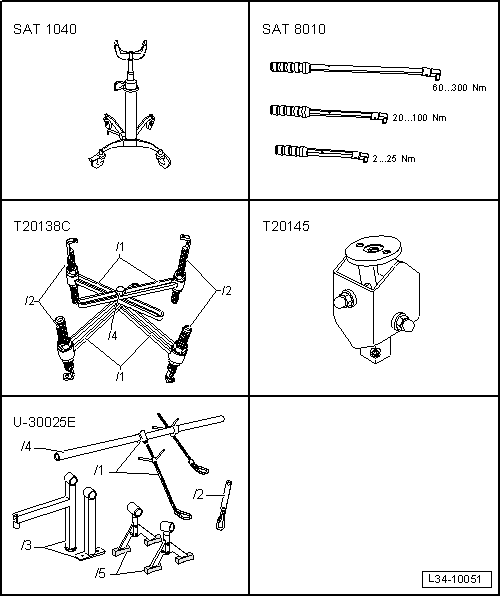
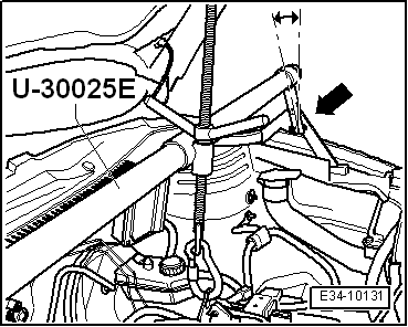
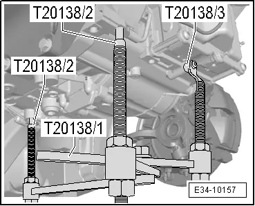
Adapter for the hydraulic engine and gearbox jack -SAT 1001/1-
Operation process
  Note
t  Observe rules for cleanliness when working on gearbox → Chapter.
t  Refer to general repair instructions → Chapter.
t  Observe notes on dual clutch gearbox 0AM → Chapter.
t  All cable ties which are released or cut open when removing the gearbox must be refitted in the same position when installing the gearbox.
–  Raise the vehicle. In doing so, place the supports of the lifting platform at the same height.
–  Put the gear selector lever into position »P«.
–  With ignition switched off, disconnect battery earth strap.
Engine TSI, 1.4 l - 110 and 132 kW
–  Remove the air filter housing completely → Rep. gr.24 .
Engine SRE, 1.6 l - 77 kW
–  Remove the first intake manifold lower of the intake system.
All vehicles (continued):
   
–  Remove battery → Electrical system; Rep. gr.27.
–  Remove nuts-1- and bolt -2- and extract the battery holder.
–  Remove starter → Electrical system; Rep. gr.27 .
  E34-10141
–  Hang-out the selector lever control cable -2- from the lever of the selection shaft.
–  Pull off securing clip -1- for selector lever cable.
  Note
t  A lock washer, which was removed, never insert again. It could be damaged if it no longer has the necessary inner tension.
t  This is why a new circlip must always be used when assembling.
–  Remove the control cable from the counter bearing on the gearbox with great care. Do not bend it.
You can push the control cable a little out of the counter bearing to the back and remove it later when lowering the gearbox. In this case, you have to take care when lowering using the control cable.
  A34-10409
–  To unlock and remove the plug connection on the catch draw out the plug connection of mechatronics.
–  Then unscrew all upper securing bolts between engine and gearbox.
  N34-10956
One screw is located in the opening of the starter. The socket -T10061- can be used instead of the 18 mm socket.
–  Remove the centre sound insulation → Bodywork, exterior installation work; Rep. gr.50
–  Remove the left and right wheel box cover → Exterior body installation work; Rep. gr. 66
  N34-10965
The number of electrical connectors on the bracket described below may vary depending on the engine model.
–  Remove all brackets in front of the plug connection of the gearbox.
–  Remove articulated shaft from the flange shaft of the gearbox → Running gear, shafts, steering; Rep. gr. 40 .
–  Dismount the front subframe → Front wheels suspension; Rep. gr.40 .
Engines 1.4 l - 110 kW TSI and 1.4 l - 132 kW TSI
–  Remove the front section (catalytic converter) of the exhaust system →  4 Cyl.Injection engine (1.4 l, 4 direct-injection valves, turbo and rotary piston compressor); Rep. gr.26
Engine 1.6 l - 77 kW SRE
–  Remove the front section of the exhaust system →  4 Cyl.Injection engine(1.6 l. 4V, Chain transfer); Rep. gr.26
All vehicles (continued):
–  Remove the front section of the exhaust system on the undercarriage.
–  If necessary, the engine cover may have to be removed depending on the engine version.
–  Separate the hoses and cables that may be in the area of the engine where the rings that grip the support -U-30025E - go.
  N34-10966
–  Fit the Support -U-30025E -. The adjustable position of the feet must be inclined to the back -arrow- when doing so.
  Note
t  Fit the supporting equipment so that it is seated correctly on the hardest parts of the wing water drains and will not cause any damage.
t  Ensure that the pipe connections and the cables in the area where the engine is suspended do not suffer any damage while fitting the hooks of the support equipment.
–  Slightly tense the engine assembly/gearbox via the spindles.
  E34-10131
–  Extract the attachment bolts -arrows- for the gearbox support. Always replace.
  E34-0288
–  Unscrew screw -1- of the console -A- of the gearbox.
–  Lower the engine assembly/gearbox with the spindle until the gearbox console attachment bolts -2- an be accessed from the wheel housing.
–  Unscrew the securing screw -2- of the gearbox console -A- and remove the console.
  E34-10151
–  Attach the support tool -T20138C- on the base - T20145-, and move these onto the engine and gearbox jack -SAT 1040- using the adapter for the hydraulic engine and gearbox jack -SAT 1001/1-.
–  Unscrew the remaining lower securing bolts between engine and gearbox.
–  Release the gear box from the centring cases and turn toward subframes, move the spindles of the gear box carrier -T20138C -
There are brackets on the front side of the gearbox with certain versions.
  Note
Lower the gearbox very carefully.
  E34-10157
–  When fitting a new gearbox, remove this bracket as it is no longer required.
  N34-10978
–  Renew the needle bearing of the crankshaft → Rep. gr.13 .
  N34-10979

Installing gearbox > < Gearbox?: removing and fitting