| t
| Central diagnosis -VAS 505X- |

Note | t
| Observe rules for cleanliness when working on gearbox → Chapter. |
| t
| Refer to general repair instructions → Chapter. |
| t
| Observe notes on dual clutch gearbox 0AM → Chapter. |
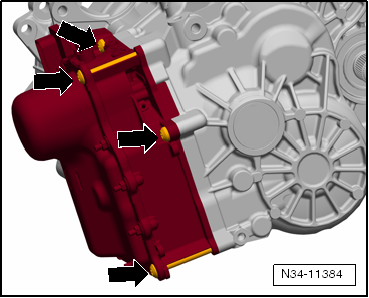
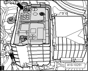
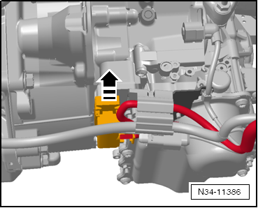
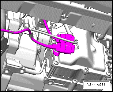
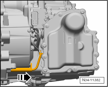
| In order to remove the mechatronic unit, sufficient space must be available in front of the gearbox. Depending on the vehicle, parts must be removed which do not have anything to do directly with the gearbox. These are, for example, the air filter as well as the charge air lines or refrigerant lines that may be installed. |
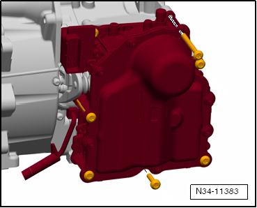
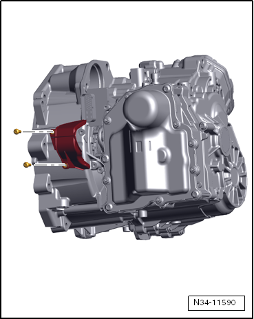
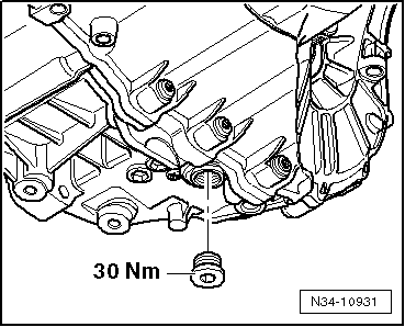
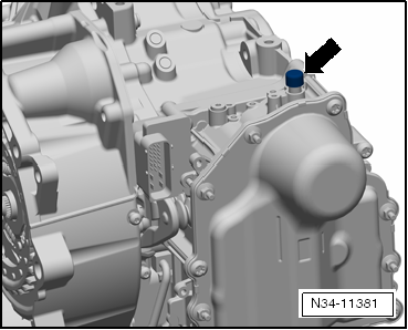
| Any retainers fitted to the bolts in the cover of the mechatronic unit must be removed. |
| Tester moves all gear actuators »into neutral«. |
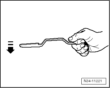
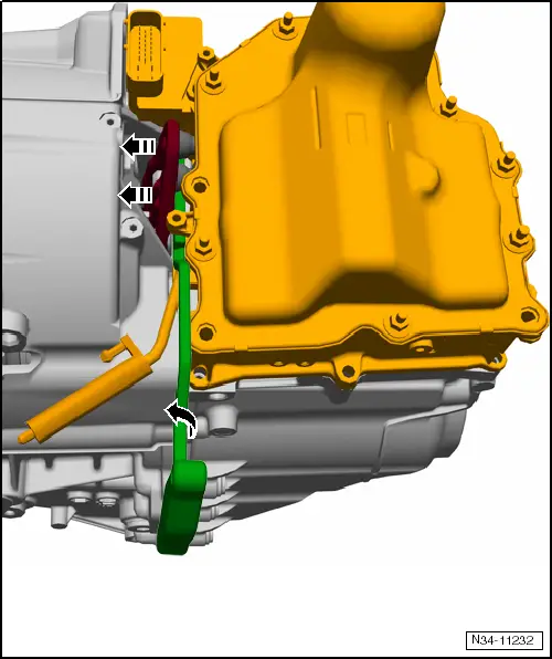
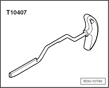
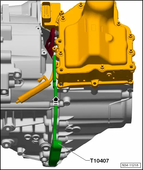
| The assembly lever -T10407- must be inserted between the clutch lever and the gearbox housing in this position. This makes it possible to remove load from plungers of mechatronic unit so that they may be removed by hand from cups of engaging levers. |
| Mechatronic unit can be removed and inserted. When installing, make sure clutch plunger is correctly seated in cup of engaging levers. |
| Therefore, please follow description below step by step. |
Note | t
| The clutch is self-adjusting. As the readjusting equipment can be influenced by any type of vibrations, it can also be influenced by »suddenly moving away « the 16 mm open-end wrench -T10241- from under the engaging lever, even when the mechatronic has been removed. |
| t
| In order to remove the mechatronic unit, sufficient space must be available in front of the gearbox. In some vehicles, parts must be removed which do not have anything to do directly with the gearbox. Remove any charge air lines or coolant lines that may be present. |
| t
| Any retainers fitted to the bolts in the cover of the mechatronic unit are also removed. |
| t
| A »new« mechatronic unit is correctly filled with oil. |
| t
| Do not drain oil. A »removed« mechatronic unit is sent back with its oil in. |
| Mechatronic unit remains filled with oil. |
| –
| Raise vehicle. All 4 supports of lifting platform must be at same height. |
| –
| Put the gear selector lever into position »P«. |
|
|
|

 WARNING


 Caution