seat Workshop Repair Guides

SEAT Workshop Service and Repair Manuals

Final drive, differential, differential lock > < Removing and installing valve chest
Automatic gearbox 099 four-wheel drive
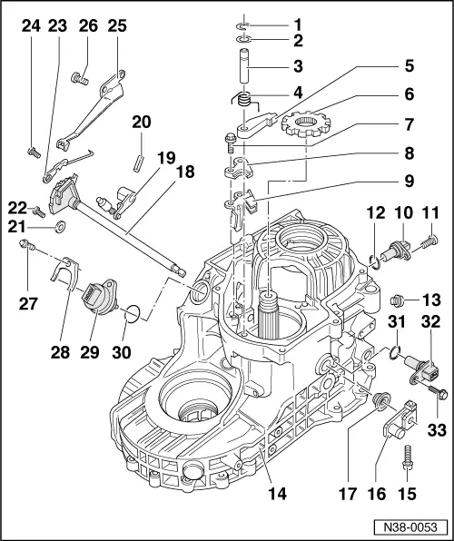
Dismantling and assembling parking lock
 
W00-0427

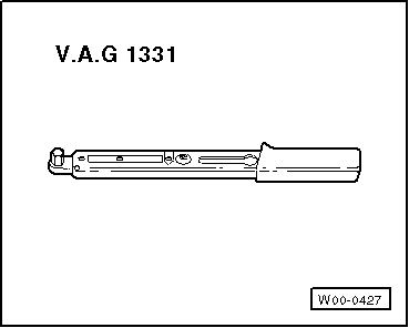
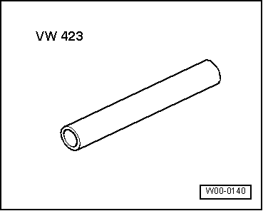
Special tools and workshop equipment required

  • ◆ V.A.G 1331 Torque wrench

 
W00-0140
  • ◆ VW 423 Tube
 
N38-0053
  • ◆ The output gear must be removed to dismantle and assemble the parking lock => Removing and installing drive pinion, Page 39-37.
  • Circlip
    • ◆ Always replace
  • Washer
  • Shaft for detent lever
    • ◆ Is secured by circlip and bearing cap of drive pinion
    • ◆ According to version with groove for circlip
  • Return spring
    • ◆ Inserting => Fig.4
  • Detent lever
    • ◆ Inserting with return spring
      => Fig.4
 
N38-0053
  • Parking lock gear
    • ◆ Rounded side faces teeth of drive pinion
  • Bolt, 14 Nm
  • Supporting plate
    • ◆ Installing => Fig.3
  • Guide plate
    • ◆ Insert before supporting plate => Fig.3
  • Road speed sender -G68-
    • ◆ Tested in the vehicle by self-diagnosis

=> Repair group 01; Performing self-diagnosis; Read measured value block

  • Bolt, 10 Nm
  • O-ring
    • ◆ Always replace
 
N38-0053
  • Bolt, 15 Nm
    • ◆ With sealing ring
    • ◆ Always replace
  • Gearbox housing
  • Bolt, 10 Nm
  • Lever
    • ◆ For selector shaft
  • O-ring
    • ◆ Lever out with screwdriver
    • ◆ Drive in flush with VW 423
  • Selector shaft with selector segment and detent segment
    • ◆ Insert together with engaging lever
    • ◆ Removing and installing => Fig. 2
  • Engaging lever
    • ◆ Insert together with selector shaft and detent segment
 
N38-0053
  • Spring pin
    • ◆ Drive in after inserting engaging lever => Fig.1
    • ◆ Drive out with drift
  • Locking washer
    • ◆ Removing and installing => Fig. 2
  • Bolt, 10 Nm
  • Manual selector valve control
    • ◆ Adjusting , Removing and installing valve chest
    • ◆ Always renew steel spring => Fig. 5
  • Bolt, 10 Nm
  • Spring for selector segment
  • Bolt, 10 Nm
  • Bolt, 10 Nm
  • Retainer
    • ◆ For multi-function switch
 
N38-0053
  • Multi-function switch -F125-
    • ◆ To remove
    • ‒ Remove insulation tray
    • ‒ Pull connector off and place oil tray under gearbox
    • ‒ When installing ensure connector is correctly sealed
    • ‒ After installing top up ATF => Page 37-52
    • ◆ Insert so that 1 pin each is resting on a slope of the detent segment
    • ◆ Tested in the vehicle by self-diagnosis

=> Repair group 01; Performing self-diagnosis; Read measured value block

  • O-ring
    • ◆ Always replace
 
N38-0053
  • O-ring
    • ◆ Always replace
  • Gearbox speed sender -G38-
    • ◆ Tested in the vehicle by self-diagnosis

=> Repair group 01; Performing self-diagnosis; Read measured value block

  • Bolt, 10 Nm
 
V38-0766

→ Fig.1    Driving spring pin (arrow) out and in

Driving out

  • ‒ Drive spring pin for engaging lever out only so far as to remove the selector shaft.

Spring pin of engaging lever may drop into planetary gearbox.

Driving in

  • ‒ Drive in spring pin flush after inserting selector shaft and engaging lever.
 
V38-0762

→ Fig.2    Removing and installing selector shaft with detent and selector segments

With valve chest installed do not damage the conductor strip.

  • ‒ Remove selector segment spring -A-.
  • ‒ Remove screw with washer (arrow).

The washer prevents selector shaft movement.

 
N38-0134

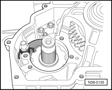
→ Fig.3    Inserting guide plate and supporting plate

 
N38-0135

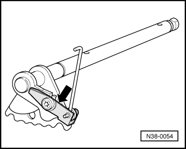
→ Fig.4    Inserting pawl with return spring

 
N38-0054

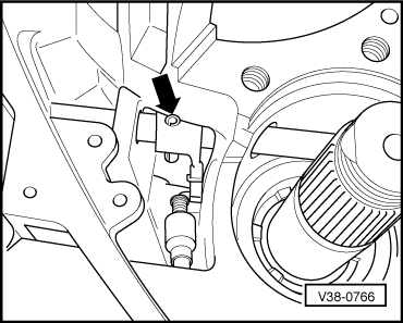
→ Fig.5    Always renew steel spring -arrow-

Final drive, differential, differential lock > < Removing and installing valve chest