seat Workshop Repair Guides

SEAT Workshop Service and Repair Manuals

Measuring distance between propshaft and steering box and adjusting > < Adjusting differential
Automatic gearbox 099 four-wheel drive
Removing and installing propshaft
 
V39-1366

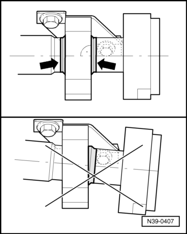
A twin pillar lifting platform should be used when working on the propshaft.

  • ◆ Before removing, mark the positions of all parts in relation to each other. Reinstall in the same position otherwise imbalance will be excessive, the mountings could be damaged causing rumbling noises.
  • ◆ → Do not unbolt propshaft on one side only and do not allow to hang down otherwise the centralizing sleeves (arrow) will be destroyed. Tie up parts if necessary.
  • ◆ Keep propshaft straight, only store and transport fully extended.
 
N39-0310
  • ‒ Release handbrake, selector lever in position "N".
  • ‒ → Mark position of front and rear propshafts between bevel box output flange and rear viscous coupling joint disc flange -arrows- (the illustration shows the joint between the two propshafts).

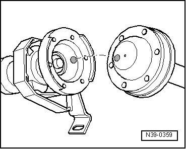
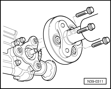
Removing front propshaft

Removing rear propshaft => Page 39-91

Removing front propshaft

 
N39-0311
  • ‒ → Unbolt front propshaft from bevel box.
  • ‒ Remove front/rear propshaft connecting bolts.

 
N39-0312
  • ‒ → Turn propshaft until flange cut-out is pointing down.
  • ‒ Remove one intermediate bearing securing bolt, loosen the second bolt (arrows) to enable the front propshaft to be taken out.

If only the front propshaft requires removing, screw intermediate bearing bolts in again to prevent the rear propshaft from falling.

Removing rear propshaft

 
N39-0408
  • ‒ → Unbolt propshaft from viscous coupling.

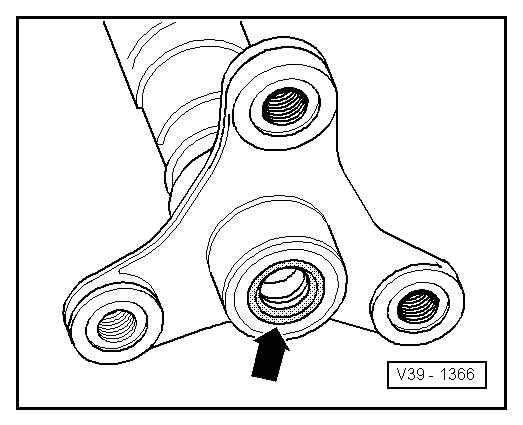
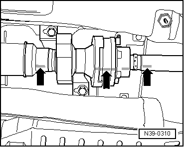
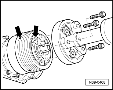
The three marks in the grooves align with the threaded holes for securing the propshaft (arrows).

  • ‒ Remove front/rear propshaft connecting bolts.
  • ‒ Remove intermediate bearing securing bolts and remove rear propshaft.

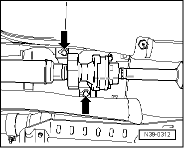
Secure front propshaft against falling if only rear propshaft is to be removed.

 
V39-1366

Installing

Installation of the propshaft is carried out in the reverse sequence.

  • ◆ → Do not damage front/rear propshaft centring sleeve/seal (arrow) during installation. Do not cant propshaft, but push horizontally onto the respective centring pin. If damaged renew respective propshaft.
  • ◆ After installing the propshaft, the distance between the propshaft and the steering box must be measured and adjusted if necessary => Page 39-94.
  • ◆ Before installing grease seal and centring sleeve (arrow).
 
N39-0359

Propshaft markings

  • ◆ → Propshaft flanges are marked with either a white or a green coloured spot.
  • ‒ When joining propshafts together ensure that the coloured spots are aligned with one another -spot on spot-.
  • ‒ Transfer coloured mark to propshaft tube if flange requires removing.

This ensures that imbalance in the complete propshaft is kept to a minimum.

Installing intermediate bearing free of stress.

  • ‒ Align the intermediate bearing within the elongated holes so that the propshaft is not under stress.
  • ‒ Tighten intermediate bearing bolts to body after propshaft has been installed.
 
N39-0407

→ The intermediate bearing is installed free of stress if the sealing lips -arrows- project evenly on both side of the bearing and the propshaft tube aligns vertically with the bearing carrier.

Tightening torques

Intermediate bearing to body

20 Nm

Front propshaft to rear propshaft

30 Nm

Flexible coupling to viscous coupling

45 Nm

Flexible coupling to bevel box/viscous coupling


45 Nm

Flexible coupling to propshaft

45 Nm

Measuring distance between propshaft and steering box and adjusting > < Adjusting differential