
Leon Mk1
|
Servicing propshaft
Servicing propshaft
|
 |
|
|
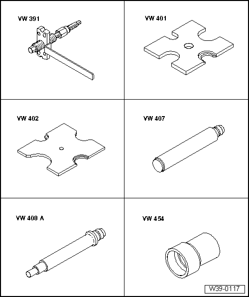
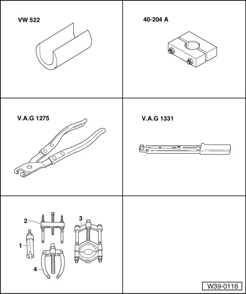
Special tools and workshop equipment required
|
 |
|
|
 |
|
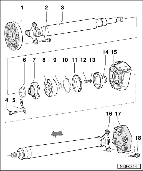
Arrows point in direction of travel |
|
|
Do not use hexagon bolts. Arrows point in direction of travel |
|
|
Arrows point in direction of travel |
|
|
Arrows point in direction of travel |
|
|
Arrows point in direction of travel |
|
|
Do not use hexagon bolts. Arrows point in direction of travel |
 |
|
|
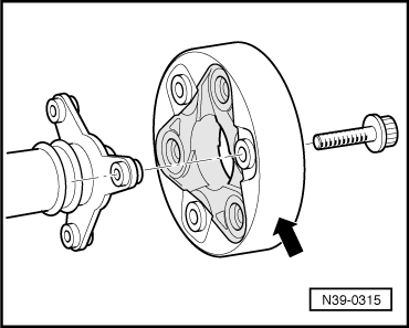
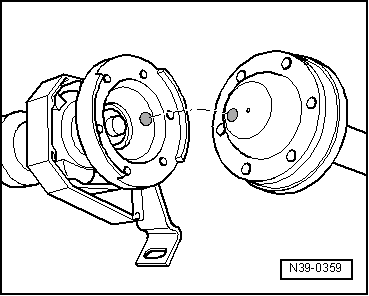
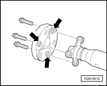
→ Fig.1 Front flexible coupling installation position
|
 |
|
|
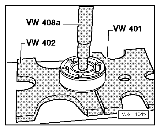
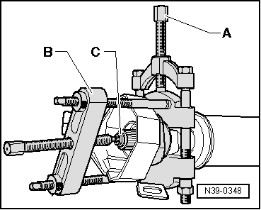
→ Fig.3 Pressing off constant velocity joint |
 |
|
|
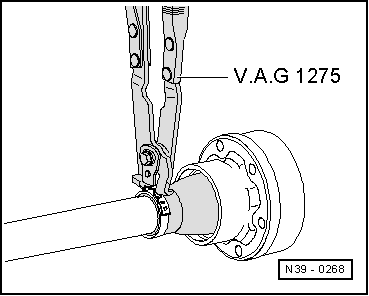
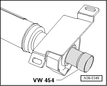
→ Fig.5 Tensioning clamp Allocate clamp in repair cases via parts catalogue. |
 |
|||||||||
|
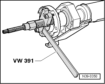
→ Fig.6 Pulling intermediate bearing off
| |||||||||
 |
|
|
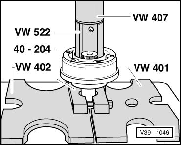
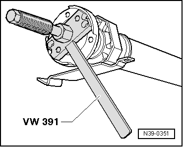
→ Fig.7 Driving intermediate bearing on
|
 |
|
|
→ Fig.8 Pulling flange off |
 |
|
|
→ Fig.9 Pulling flange on |
 |
|
|
→ Fig.10 Rear flexible coupling installation position
|