seat Workshop Repair Guides

SEAT Workshop Service and Repair Manuals

Repairing selector mechanism > < Selector lever handle and gear operation mechanism cover: Assembly overview
Gearbox, for vehicles with turbo diesel engine. Install
Install in reverse order, observing following:
  Note
t  Clean ATF pipes and ATF cooler before installing a replacement gearbox → Chapter.
t  
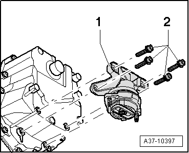
Always replace self-locking nuts and bolts during assembly.
t  Renew oil seals, gaskets, O-rings and bolts which are tightened by turning through a specified angle.
t  Clean the teeth of the gearbox drive shaft and the teeth of the dual mass flywheel, remove any corrosion and apply a fine layer of grease. Allocation → Spare parts catalogue. It is essential to remove excess grease.
t  Secure hose unions with hose clamps the same as those of the series → Current Spare parts catalogue.
t  Re-attach all cable ties at the same locations when re-installing.
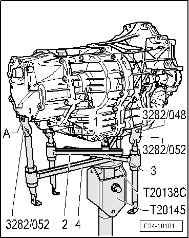
–  Check whether there are adjusting sleeves in the engine for centring the engine/gearbox assembly and fit if necessary.
–  Before installing gearbox, tie electrical wiring off to one side so that it cannot be trapped between engine and gearbox.
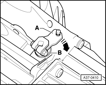
–  Lift gearbox high enough to be able to install selector lever cable.
   
–  Press selector shaft lever -A- at gearbox to rear as far as it will go -arrow- until parking lock engages.
  Note
Item -B- can be disregarded.
  Note
t  Do not bend the selector shaft lever when pressing on the selector lever cable, as otherwise it will no longer be possible to precisely adjust the gear selector mechanism
t  Do not bend or twist the selector lever cable.
t  Before fitting, lubricate the ball socket of the selector lever cable with polycarbamide grease. Allocation → Spare parts catalogue.
  A37-0410
–  Press ball joint of the selector lever cable -1- onto selector shaft lever.
–  Tighten the securing screws -2- of the bracket of the selector lever cable -1- to 23 Nm.
  E37-10047
–  Carefully lift the gearbox support -T20138C- and move to the fitting position.
  Note
t  The tightening torques only apply to lightly greased, oiled, phosphated or blackened nuts and bolts (tightening torques → Anchor).
t  Additional lubricants may be used, for example engine or gear oils, but they should never contain graphite.
t  Use is never to be made of degreased parts.
t  Tolerance for tightening torques: ± 15 %.
–  Tighten the connecting bolts on the flange between the engine and the gearbox to the specified tightening torque (Tables) → Anchor.
  E34-10181
–  Screw the bearing -1- with bolt -2- to the gearbox with the respective tightening torque → Anchor.
–  Install ATF pipes with new O-rings → Chapter.
–  Install the particulate filter → Exhaust system; Rep. gr.26.
–  Fit the complete half-shafts → Running gear, axles, steering; Rep. gr.40.
–  Install the cross-member of the gearbox using the respective tightening torque → Chapter.
–  Align exhaust system without tension → Rep. gr.26
–  Electrical connections and routing → Current flow diagrams, Electrical fault finding and Fitting locations.
–  Take all the necessary precautionary measures when connecting the battery → Electrical system; Rep. gr.27.
–  Check selector lever cable adjustment → Chapter.
–  Check oil level in front final drive → Chapter.
–  Check and top up ATF level → Chapter.
Securing gearbox to engine (illustration shows gearbox flange)
  A37-10397
Vehicles with 2.0 litre turbo diesel engine:
  A37-0075
ItemBolt.Nm
1M10x6045 → Remark
2, 3, 4, 6, 11M12x6765 → Remark
5M12x11065 → Remark
7M10x5045 → Remark
8 … 10M10x4545 → Remark
Adowel sleeves for centring

1)  Renew bolts
Specified torques
   
ComponentNm
Bolts/nutsM610
 M820
 M10:45
 M1265
Except for the following: 
Bracket for selector lever cable to gearbox23
Drive shaft heat shield to gearbox 23


Repairing selector mechanism > < Selector lever handle and gear operation mechanism cover: Assembly overview